
EagerLED Academia
Configuração do sistema de controle de displays de LED: mapeamento e testes do painel.

Mar
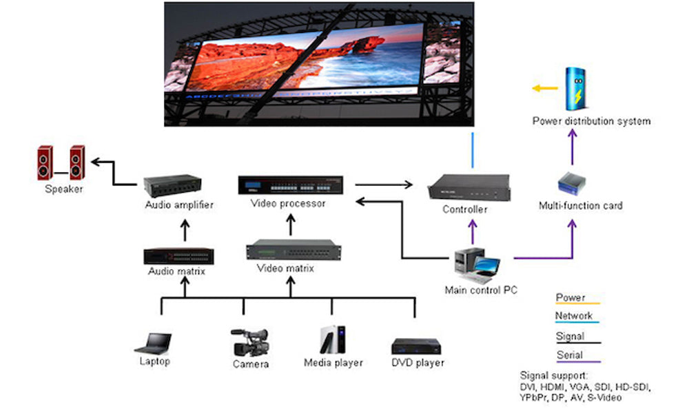
A correctly sized LED controller can still show the wrong image if its cabinet map follows the wrong cable route. When commissioning a wall, start by drawing the path from each sending port to the first cabinet and then to the last cabinet on that chain.
1. Record the physical signal path
Label every sending port and cabinet from the audience side. Also mark where the technician stands when viewing the wiring from behind. A row that runs left to right from the front appears reversed from the rear. Photographs of the cable labels can resolve this ambiguity during a later repair.
2. Identify the software and receiving-card configuration
Read the sending-device and receiving-card labels before opening a configuration tool. A Huidu or Linsn installation needs software and files appropriate to its own hardware. A video processor upstream, including a compatible RGBlink processor, supplies the picture to the sending stage. Its video output settings alone do not define the wiring inside each cabinet.
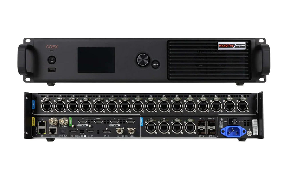
Save the working screen map and receiving-card parameters when available. Keep an untouched copy with the hardware revision and date. For a replacement cabinet, confirm the module driver, scan arrangement and hub connections before applying a file to one receiving card.
3. Map the wall before adjusting the source
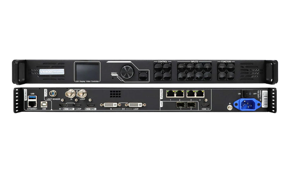
Enter the cabinet’s native pixel dimensions and assign each cabinet to its real port and cable position. For example, four cabinets wide by two high, each with a 128 × 128 matrix, form a 512 × 256 canvas. That calculation gives the image size. The cabling drawing determines where each part appears.

Use a labelled grid with distinct corners. If the whole image is cropped but every cabinet is in the right place, inspect source scaling. If the correct pieces appear in the wrong order, compare the screen map with the physical chain.
4. Test and hand over the configuration
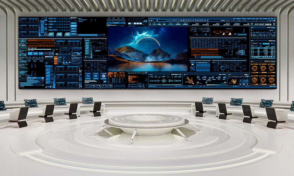
Check primary colours, solid grey and a moving image at the operating brightness. Save the verified configuration using the software’s documented persistence procedure. Agree a maintenance window for a restart test, then hand over the map, port labels and backup files together.
5. Perguntas frequentes
(1) Why does the middle row appear backwards?
A common cause is a mismatch between the configured row direction and a zigzag cable route. Trace the first and last cabinet on that row and compare their positions with the map.
(2) Can the video processor correct two swapped cabinets?
Reassign the cabinet positions in the screen map or correct the cabling to match the drawing. Changing the source crop affects the picture before it reaches those positions.
(3) What should I keep before replacing a receiving card?
Keep the exact card and module identifiers, the working parameter file, a copy of the screen map and a photograph of the connectors. Verify the replacement on one cabinet before expanding the change.
6. Conclusão
A labelled grid and a front-view cable drawing make commissioning repeatable. When the physical chain and software map agree, the next technician can isolate a source, port or cabinet fault without rebuilding the whole wall.