
EagerLED 教學
LED 顯示器控制系統完整指南

LED display control systems move content from a live video source or a stored-media player to the receiving cards that drive an LED screen. For an AV integrator preparing a system purchase, the starting points are the screen’s native pixel dimensions, the required playback workflow and the existing receiving hardware. A controller’s product name alone does not establish compatibility.
Video processing and sending control can be separate functions or integrated in one device. A receiving card remains part of the screen-side signal path. Buying a sending card, a controller and a video processor as three separate boxes is therefore not a universal requirement. First identify which functions the proposed equipment already includes.
This guide explains how to compare LED display control systems for a new installation or an equipment replacement. The original photographs illustrate component types; they do not establish a tested configuration, an included accessory list or compatibility between the pictured devices.
1. How LED Display Control Systems Connect
A typical live-video path is source → video processing, when required → sending controller → receiving cards → module connections. In an all-in-one controller, the processing and sending stages share one enclosure. In a signage player, stored-media playback and sending may also be integrated. Follow the connection diagram for the exact equipment rather than inserting extra devices into every system.
Separate the video path from the management connection. A computer connection used to configure a controller is not necessarily the connection that supplies its displayed video. Labels such as INPUT, OUTPUT, CONTROL and LOOP describe different jobs. Document those jobs before preparing cables or deciding how an operator will change content.
| 元件 | Job in the system | 買方應確認的內容 |
|---|---|---|
| Video source or player | Supplies live video or plays prepared content | Live input format, or supported file formats and scheduling workflow |
| 視訊處理器 | Handles the processing functions specified for that model | Whether scaling, switching or layers are needed and already included elsewhere |
| Sending card or controller | Sends configured display data toward compatible receiving cards | Input support, port loading, screen mapping and supported receiving hardware |
| 收款卡 | Connects the sending system to module or hub-board data connections | Exact board, connectors, configuration and module requirements |
These distinctions matter when comparing LED display control systems across listings. Two products may both be called controllers while one accepts live video and another primarily plays stored content. Ask for a signal-path drawing with the quoted model numbers if the proposed arrangement is unclear.
2. Selecting an LED Sending Card
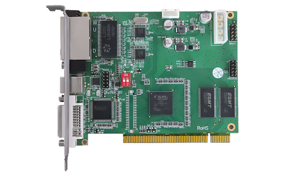
An LED發送卡 is part of the transmission stage between the video system and the receiving cards. It should not be described as a universal video scaler, media decoder or automatic image enhancer. Which functions are available depends on the particular card or sending box and its supported software.
01. Match the source input
Check the actual input connectors and their supported signal formats. NovaStar’s published MCTRL600 product information, for example, identifies HDMI and DVI inputs. That does not establish DisplayPort or SDI support for the MCTRL600, nor does it describe every other sending device. Use the exact model’s input table when preparing a source connection.
Specify the source resolution, refresh rate and bit depth together. A connector name by itself is incomplete purchasing information. Also distinguish a control USB connection from video input or media playback. If a converter or adapter is proposed, include it in the system review instead of assuming it preserves every required signal feature.
02. Separate loading capacity from scaling
Pixel loading describes the display data a device can handle under stated conditions. Scaling describes resizing an image. A sending card’s loading capacity does not prove that it automatically fits an incoming picture to the screen. Check the source settings or provide suitable processing when resizing is required.
For LED display control systems, record both total pixel area and the proposed port allocation. A screen may fit a headline total while its intended wiring still needs review. Ask the supplier to check the layout against per-port limits, maximum dimensions and the required operating mode, rather than approving the purchase from a total-pixel figure alone.
03. Check timing without assuming zero latency
For a live camera or presentation, ask which timing and synchronization functions the selected equipment supports. Input frame rate, screen refresh behavior and end-to-end delay are different questions. A high refresh-rate claim is not evidence of zero delay, and a more expensive sending card does not automatically remove every motion artifact.
3. Choosing the Playback and Control Workflow
競品對比 LED screen controllers by the work they must perform. Live operation may require source switching and operator control during an event. Scheduled signage may require local media storage, playlist publishing and a defined recovery process after an interruption. Start with that workflow before comparing extra features.
01. Live video and stored content
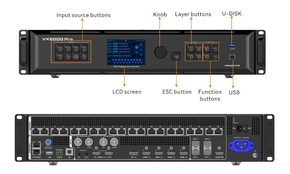
In common product terminology, synchronous operation uses an external live source, while asynchronous operation plays prepared content from a player. Some models support both. NovaStar’s TB40 specifications V1.2.1 describe an internal source in asynchronous mode and an HDMI source in synchronous mode. This is a model-specific example, not a promise that every signage player accepts HDMI.
When specifying LED display control systems for an unattended installation, ask what happens when the network is unavailable, a source disconnects or power returns. Request the documented behavior for the quoted configuration. Define who publishes content and who can restore operation; remote access is a workflow requirement, not simply a checkbox on a product comparison.
02. Integrated control and processing
NovaStar’s VX600 User Manual V1.4.0 describes integrated video processing and control, including scaling and multiple working modes. This supports choosing an all-in-one arrangement when its documented functions fit the project. It does not mean that every device labeled controller has those functions, or that a feature remains available in every mode.
Before adding a separate processor, list what the selected controller already does and what remains missing. Confirm how presets, switching and configuration will be handled during operation. An unnecessary box adds connections and operating steps; an omitted processing function can leave the source unable to fit the intended screen canvas.
4. When a Separate LED Video Processor Helps
單獨 LED視頻處理器 is worth considering when the planned system needs processing that its sending equipment does not provide. Examples of requirements to check include source switching, scaling, cropping and multiple picture layers. Their availability, combinations and limits must come from the proposed model’s documentation.
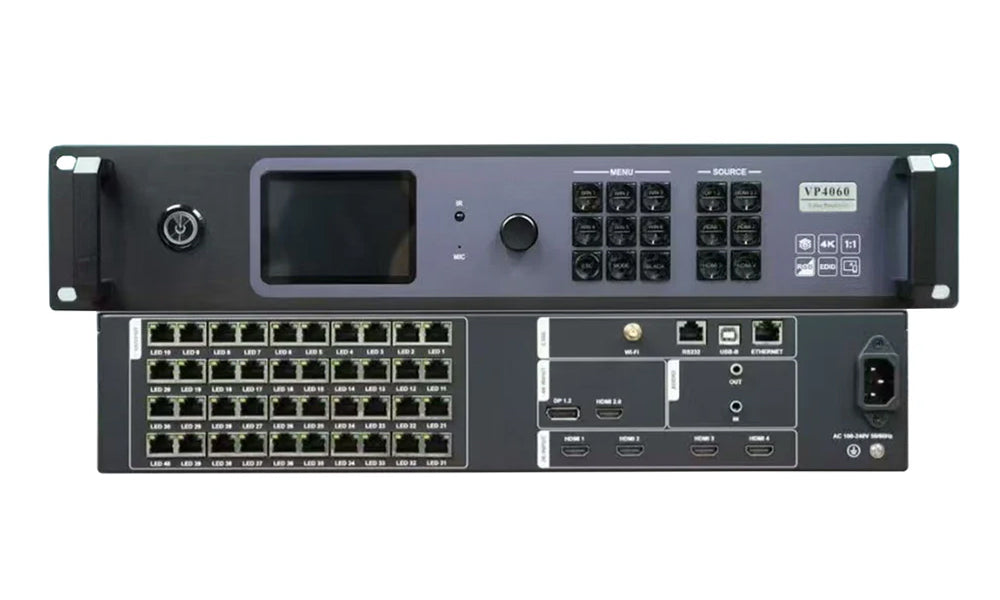
Do not assume a processor improves every source or reduces latency simply because it processes video. Define the required operation first: fit a presentation to an unusual screen shape, switch between two sources, or position a live camera window. Then verify that the chosen device supports that operation with the actual input and output settings.
When comparing LED display control systems, separate input acceptance from output capability. A specification for decoding a media file does not establish the maximum live HDMI input. Similarly, accepting a large input does not establish the screen size that the sending stage can drive. Request a complete source-to-screen configuration instead of joining unrelated headline specifications.
Agree on how an incorrectly sized source should appear: cropped, scaled or positioned within the canvas. Preserve the aspect ratio where required. An image can fill the screen and still be stretched or lose useful content. Include a representative presentation or camera signal in the acceptance plan, alongside a test pattern.
5. Receiving Cards and Module Compatibility
LED display control systems need a compatible receiving stage. NovaStar’s MRV328 Specifications V1.2.7 identify Gigabit Ethernet connections to the sending card and eight HUB75E connectors for module communication. Other boards and cabinets may use different arrangements. A similar-looking connector or a matching brand name alone is insufficient evidence of interchangeability.
For a replacement in LED display control systems, collect the current card model, board revision where shown, clear PCB and connector photos, module information, hub-board details and saved configuration. Include the known working software and firmware versions. A replacement request based only on pixel pitch leaves the supplier without enough information to assess the existing display.
Ask the supplier to confirm the proposed replacement against those records and agree on a sample check before bulk purchasing. Keep the original working files and record the test configuration. If a saved file can be read back, preserve it before making changes; whether readback is available depends on the hardware, software and file involved.
瀏覽 LED接收卡類別 as a starting point for matching models. Treat a category listing as a product-finding aid, not confirmation that every card in it works with an existing screen. Written confirmation should identify the proposed combination and its conditions.
6. A Buying Checklist for LED Display Control Systems
Give each supplier the same project brief so that quotations can be compared on a consistent basis. Begin with the native screen width and height in pixels, the cabinet arrangement, the intended source and the operating workflow. Physical dimensions and pixel pitch are useful context but should not replace the actual pixel canvas.
| Prepare | 請供應商確認 | Keep in the purchase record |
|---|---|---|
| Native pixel width and height; cabinet layout | Total capacity, dimensional limits and port allocation for the proposed settings | Model-specific loading plan |
| Source connector, resolution, frame rate and bit depth | Input support and any required processing or conversion | Input/output settings and adapter details |
| Live, local-playback or remote-publishing workflow | Required mode, software and connectivity | Operating procedure and responsibility for configuration |
| Existing receiving card, module and hub-board records | Compatibility conditions and sample acceptance procedure | Board identities and configuration files |
| Required accessories and backup behavior | What is included, optional or supplied separately | Itemized package and agreed test plan |
For example, a hypothetical screen measuring 1,920 by 1,080 pixels contains 2,073,600 pixels. That arithmetic is only a starting point. It does not verify a particular controller, port map, bit-depth setting or backup arrangement. Send the full layout for confirmation rather than treating the multiplication as a compatibility result.
Specify the exact model suffix and hardware version on the quotation. Similar model names do not prove identical connectors, functions or software support. Ask which specification revision supports the offer, and separate the stated standard package from optional fiber modules, sensors, wireless modules, cables or mounting accessories.
The best comparison of LED display control systems is a comparison of confirmed configurations. Price, availability, delivery, warranty and technical support should be confirmed for that quotation. Do not assume those terms from a general guide or an older product description.
7. Commissioning and Troubleshooting
Before commissioning LED display control systems, document the connection order and preserve existing working settings. The original diagram below illustrates a signal-chain concept; it is not a wiring instruction for every cabinet. Use the selected equipment’s connection diagram and the screen manufacturer’s configuration records for the actual installation.
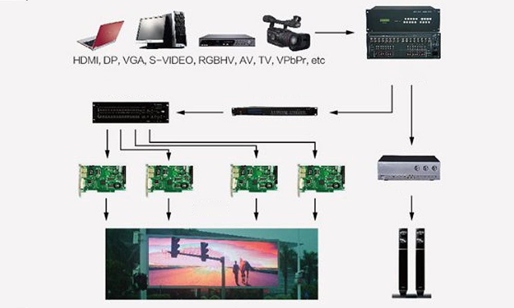
Begin with an agreed source and a known configuration, then verify the displayed canvas and cabinet order. Check a test pattern and representative content. Record which settings were used and what was observed. This creates a useful baseline for future troubleshooting without claiming that a successful test proves compatibility under every possible operating condition.
If the picture is missing, scrambled or unstable, isolate one stage at a time. Check whether the source is detected, whether the selected input and mode are correct, and whether the port mapping matches the wiring. Receiving configuration, module connections, signal cabling and power conditions may also need investigation. A controller change alone is not a universal cure.
Firmware should follow a documented reason and the manufacturer’s procedure for the exact hardware. Record the current versions and back up supported configuration data before changing anything. Confirm the update package and recovery procedure; do not update solely because a newer file exists or assume another board’s configuration is safe to reuse.
For replacement hardware, agree on acceptance criteria before the old equipment is removed. Decide what must be checked during a sample trial and how the known working arrangement can be restored if the trial fails. Have qualified personnel address electrical or installation issues; this purchasing guide does not replace project-specific engineering.
8. 將系統與應用程式相符
Application labels help start a discussion, but LED display control systems should be specified around the required signals and operator tasks. A venue using live cameras has different priorities from a store updating a playlist. A control room may need a defined source layout and a clear procedure for restoring that layout after maintenance.
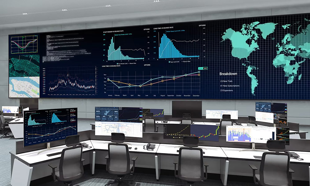
For a meeting space, include the presentation sources and the person responsible for switching them. For scheduled signage, include content publishing and local playback requirements. For an event, describe the live signal path and the required backup behavior. These details are more actionable than requesting a controller for an indoor or outdoor screen alone.
When planning upgrades to LED display control systems, ask what specific capability is missing. Higher input resolution, remote management and automated brightness control are separate requirements. Verify each against the proposed hardware and software instead of assuming that an AI label, cloud feature or newer product generation improves every part of the installation.
常見問題
Does an RJ45 LED output connect to a normal network switch?
Do not assume so from the connector shape. LED data outputs and a management Ethernet port can have different purposes. Follow the manufacturer’s supported topology and ask for the correct connection diagram before inserting network equipment into the display data path.
Will adding a processor remove flicker?
That is not a reliable purchasing assumption. First establish whether the problem involves the source, timing, receiving configuration, module driving or another part of the installation. Specify a processor to provide an identified missing function, and test the proposed arrangement against the observed problem.
Can a new receiver use the old configuration file?
Do not treat the file as universally portable. Ask for confirmation against the exact receiving card, hardware revision, module and software. Preserve the old file, identify the proposed replacement and agree on a sample test before applying settings across an existing screen.
Does cloud control mean live video comes over the internet?
Not necessarily. Remote publishing, monitoring and a live video input are different functions. Specify whether you need to upload a playlist, change settings or display a live stream. Ask how the proposed equipment receives that content and what happens when its network connection is unavailable.
What should be checked before placing a repeat order?
Compare the full model and revision, the current specification, included accessories and saved configuration with the earlier order. Ask the supplier to identify any substitutions. A familiar product name or enclosure does not establish that a repeat shipment has the same hardware and operating requirements.
Prepare a Confirmed Control-System Configuration
Before ordering LED display control systems, assemble the pixel canvas, cabinet layout, source settings, receiving-card identity and playback workflow. Ask for the exact equipment combination, operating mode and package contents to be confirmed together. 聯繫我們 EagerLED with your screen and source details to discuss a configuration or replacement request.
Technical examples checked against NovaStar’s MCTRL600 product information, VX600 User Manual V1.4.0, MRV328 Specifications V1.2.7 and TB40 Specifications V1.2.1 on November 17, 2026. These examples describe those documents, not every hardware revision or current offer; confirm the documentation supplied for the model being purchased.