
V-Hub P16 LED panel HUB karta
12.00 USD
- V-Hub P16 HUB card for LED panels.
- 20-pin reference for comparing an existing board.
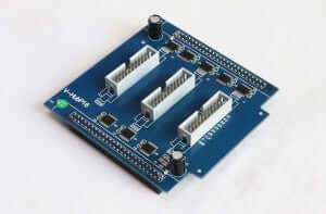
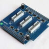
- Original photo shows the three-connector layout.
V-Hub P16 LED panel HUB karta
Use the original 20-pin interface reference to compare the V-Hub P16 LED panel HUB card with the documentation for your installed board. The original photo shows the three white connectors and their orientation on the blue board.
20-Pin Interface Reference
The table lists five groups of RD, GD and BD signals on pins 1–15. Pins 16–20 are CLK, LAT, A, OE and GND in that order.
| Zvláštní kolík | Signálu | Sudý pin | Signálu |
|---|---|---|---|
| 1 | RD1 | 2 | GD1 |
| 3 | BD1 | 4 | RD2 |
| 5 | GD2 | 6 | BD2 |
| 7 | RD3 | 8 | GD3 |
| 9 | BD3 | 10 | RD4 |
| 11 | GD4 | 12 | BD4 |
| 13 | RD5 | 14 | GD5 |
| 15 | BD5 | 16 | CLK |
| 17 | LAT | 18 | A |
| 19 | OE | 20 | GND |
Původní fotografie na tabuli
Často kladené dotazy
What signals are listed for pins 16 through 20?
The original V-Hub P16 listing assigns pin 16 to CLK, pin 17 to LAT, pin 18 to A, pin 19 to OE and pin 20 to GND.
How can I check whether the V-Hub P16 fits my panel?
Compare all 20 pin assignments and the connector orientation with your existing board. Share the installed board marking, receiving card model and LED module model if you need help checking the fit.
Request a Replacement Check
Share the installed board’s full model and revision, close views of its markings and cable orientation, and the receiving card and LED module models.
| Hmotnost | 0.2 kg |
|---|
Buďte první, kdo ohodnotí “V-Hub P16 LED Panel HUB Card”
Pro napsání recenze se musíte přihlásit .
Budu obviněn z cel a daní?
Ceny zobrazené na našich stránkách jsou bez daně (v amerických dolarech), což znamená, že po obdržení objednávky můžete být požádáni o zaplacení dovozních cel a daní. Dovozní daně, cla a související celní poplatky určí váš místní celní úřad, když vaše objednávka dorazí na místo určení.
Vezměte prosím na vědomí, že tyto dodatečné poplatky a daně jsou vaší odpovědností a my za ně nepřebíráme žádnou odpovědnost. Nejsme zodpovědní za úhradu ani proplacení jakýchkoli cel, daní ani souvisejících poplatků . Pro více informací o těchto poplatcích se prosím obraťte na váš místní celní úřad.
Přeprava
Můžeme loď prakticky na jakoukoli adresu na světě. U některých produktů existují omezení a některé produkty nelze dopravit do mezinárodních destinací.
Při zadávání objednávky odhadujeme dodací a dodací lhůty pro vás na základě dostupnosti vašich položek a možností dopravy, které si vyberete. V závislosti na poskytovateli přepravy, který si vyberete, se mohou na stránce přepravních kotací zobrazit odhady datumu dodání.
Vezměte prosím na vědomí, že ceny za dopravu u mnoha položek, které prodáváme, vycházejí z hmotnosti. Hmotnost každé takové položky je uvedena na stránce s podrobnostmi. Aby se zohlednily zásady přepravních společností, které používáme, všechna závaží se zaokrouhlí nahoru na další plnou libru.
vrací politiky
Většinu nových neotevřených položek můžete vrátit do 30 dnů od doručení a získat tak plnou náhradu. Budeme také platit náklady na vrácení zásilky, pokud je vrácení způsobeno naší chybou (obdrželi jste nesprávnou nebo vadnou položku atd.).
Měli byste očekávat, že obdržíte vrácení peněz do čtyř týdnů od doručení balíčku zpětnému odesílateli, avšak v mnoha případech dostanete refundaci rychleji. Tato časová lhůta zahrnuje dobu přejezdu, abychom mohli obdržet Váš návrat od odesílatele (5 až 10 pracovní dny), čas potřebný k zpracování vašeho vrácení po jeho obdržení (3 až 5 pracovní dny) a čas, který trvá vaši banku zpracovat požadavek na vrácení peněz (5 až 10 pracovní dny).
Pokud potřebujete vrátit položku, jednoduše se přihlaste ke svému účtu, zobrazte objednávku pomocí odkazu „Dokončené objednávky“ v nabídce Můj účet a klikněte na tlačítko Vrátit položky. Jakmile obdržíme a zpracujeme vrácenou položku, upozorníme vás e-mailem na vrácení peněz.
Související produkty

Hodnocení
Nejsou žádné hodnocení.