
Eager-LED Academy
Novastar MX20 Configuration Tips for Smoother Video Walls
Aug
Novastar MX20 configuration tips are most useful when they follow the same order as a real LED wall commissioning session. Smooth playback is not created by one “best” setting. It comes from matching the source timing, screen canvas, cabinet map, Ethernet port loads, synchronization method, bit depth, and receiving-card capabilities before the show begins.
This guide explains a repeatable NovaStar MX20 setup workflow for rental stages, studios, conference rooms, control rooms, and fixed LED installations. It is based on NovaStar’s MX20 specifications and user manual V1.5.1, released April 30, 2026, and focuses on the decisions that prevent stutter, tearing, frame jumps, uneven motion, and hard-to-recover configuration errors.
Table of Contents
- 1. Start with a Verified NovaStar MX20 Configuration Baseline
- 2. Match MX20 Input Timing to the LED Canvas
- 3. Build the Cabinet Map Before Connecting Outputs
- 4. Balance Load Across the Six Ethernet Ports
- 5. Configure Sync and Latency for Smoother Video Walls
- 6. Tune Brightness, Gamma, Color, and Bit Depth
- 7. Save MX20 Presets and Build a Recovery Workflow
- 8. Troubleshoot NovaStar MX20 Video Wall Problems in Order
- 9. NovaStar MX20 Configuration Checklist
- 10. NovaStar MX20 Configuration FAQs
- 11. Conclusion: Repeatable MX20 Setup for Smoother Shows
1. Start with a Verified NovaStar MX20 Configuration Baseline
Before opening VMP or moving cabinets on a canvas, confirm what the processor, source, cables, receiving cards, and LED modules can actually support. The NovaStar MX20 LED display controller provides two HDMI 1.3 inputs with loop outputs, one 3G-SDI input with loop, six Gigabit Ethernet outputs, and two 10G optical ports. Its maximum device load is 3.9 million pixels, with a maximum output width or height of 4096 pixels.
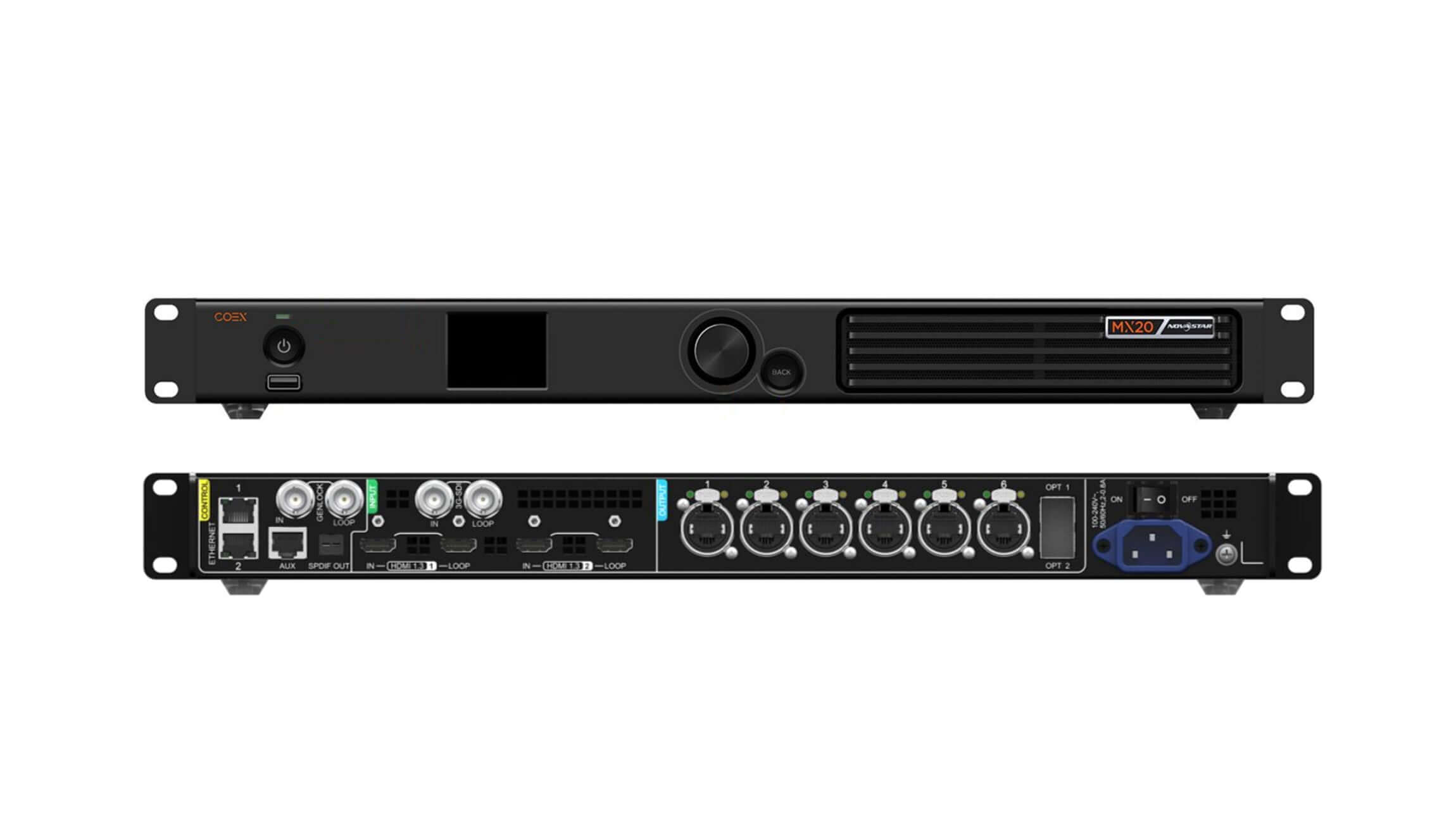
Record the firmware version, VMP version, receiving-card model, cabinet resolution, module scan type, driver IC, target frame rate, and required bit depth. If a previously working cabinet file is available, keep a verified copy outside the controller. Do not begin by updating every device just because a newer package exists; first check release notes and compatibility for the complete signal chain.
Capacity is conditional. The 3.9-million-pixel headline is not a guarantee for every format. At 8-bit, 60 Hz, one Gigabit port can load up to 659,722 pixels. At 10-bit, 60 Hz, the practical single-port figure drops to approximately 494,791 pixels with A10s Pro receiving cards and about 329,861 pixels with other Armor-series cards.
Also verify the physical path. NovaStar specifies up to 100 m for CAT5E Ethernet cable. The second optical port copies OPT 1 as a backup, and optical modules are not included by default. If the design relies on fiber redundancy, confirm matching modules, fiber type, patching, and failover behavior during rehearsal rather than assuming the duplicate output is ready.
2. Match MX20 Input Timing to the LED Canvas
Many “controller” problems start at the source. A media server may be outputting the wrong raster, a switcher may be changing frame rate between cues, or an EDID handshake may have selected a television timing that forces unnecessary scaling. Begin with the LED wall’s native canvas and work backward to the source.
2.1 Set EDID Before Scaling
For the cleanest pixel-to-pixel path, set the input resolution to match the active LED canvas whenever the source and connection allow it. In the MX20 input menu, select a standard timing or create a custom EDID, then set the required frame rate and apply the change. Recheck the source output after applying the EDID; some graphics cards require the display to be rediscovered before they expose the new timing.
If the wall canvas cannot be generated directly, choose one controlled scaling stage. Avoid scaling in the media server, switcher, and MX20 at the same time. Multiple stages can soften fine content and complicate latency measurements. Confirm the image at 100% scale using a pixel grid, single-pixel lines, and a moving test clip.
2.2 Choose All-In-One or Send-Only Mode
The operating mode changes both workflow and latency. All-In-One Controller mode includes image processing and introduces one frame of controller latency. Send-Only Controller mode is designed for a preprocessed source and can reduce controller latency to less than 1 ms when Low Latency is enabled and the loading rules are satisfied.
Use All-In-One when the MX20 must scale, layer, crop, or manage multiple inputs. Use Send-Only when a media server or upstream processor already supplies the exact output raster and minimum delay is more important than internal processing. Document the chosen mode in the show file because presets created for one signal architecture may not behave as expected in another.
3. Build the Cabinet Map Before Connecting Outputs
A cabinet map should describe the physical wall, not compensate for unverified cabling. Confirm each cabinet’s pixel dimensions and data direction, label the Ethernet runs, and decide where every port starts and ends. A clean map makes later load calculations, redundancy planning, fault isolation, and low-latency setup much easier.
3.1 Use Swift Layout Only for Regular Screens
The MX20 front-panel Swift Layout is fast, but it is intentionally limited. Use it for a regular rectangular screen made from equal-size cabinets, with the same wiring pattern on all ports. NovaStar’s rules also assume that the first n-1 ports load the same number of cabinets and that those loads form complete rows or columns.
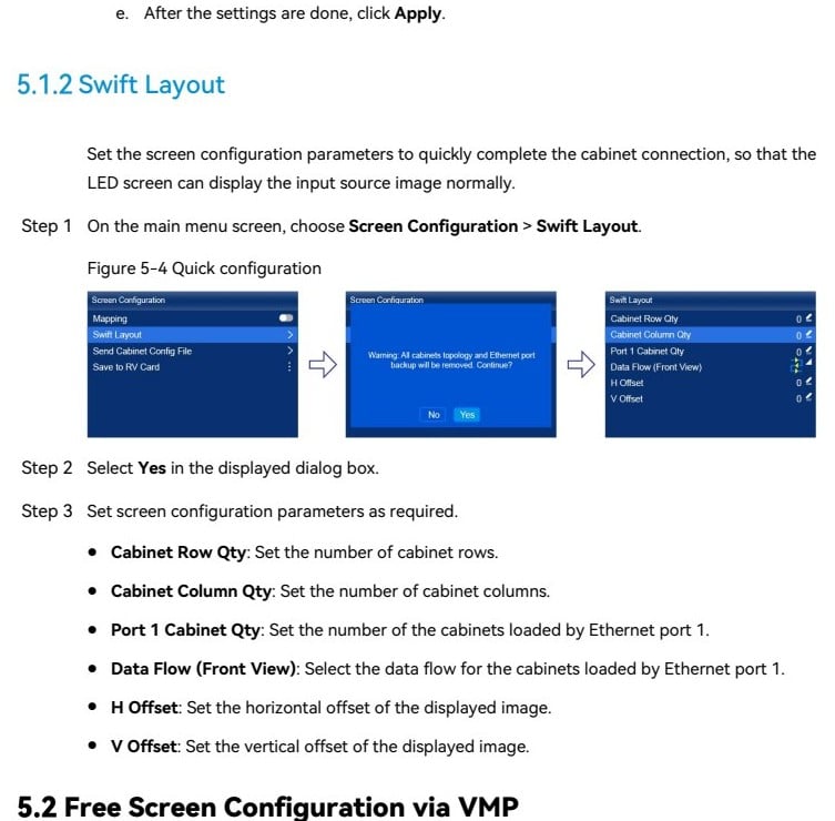
Enter cabinet rows, cabinet columns, the number of cabinets on port 1, the front-view data flow, and any horizontal or vertical offset. Then verify the result visually. If cabinets are mixed, the canvas is irregular, or ports use different paths, stop and move to VMP instead of forcing Swift Layout to approximate the wall.
3.2 Use VMP for Free Wiring and Irregular Canvases
VMP is the correct tool for free wiring, staggered cabinets, curved walls, custom canvases, and projects that need accurate used-load calculations. Create the screen from the actual cabinet dimensions, assign each Ethernet output deliberately, and keep port routes visually simple. For a broader explanation of senders, processors, and receiving cards, see EagerLED’s guide to LED display control systems.
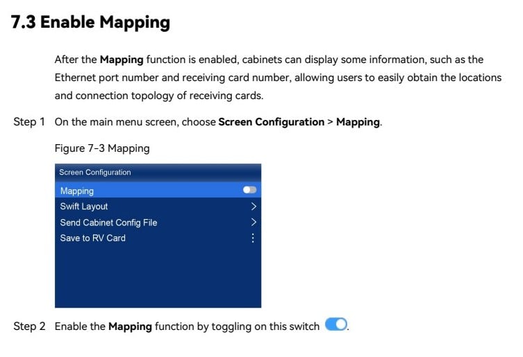
Enable Mapping during commissioning. The LED cabinets can display the Ethernet port number and receiving-card number, making it easier to compare the software topology with the physical chain. Photograph the correct mapped wall and save it with the project documentation.
4. Balance Load Across the Six Ethernet Ports
Port balance is one of the most important MX20 configuration tips for stable video walls. Do not divide cabinets by count alone. Divide by pixels, then verify the result against bit depth, frame rate, receiving-card model, and load-area geometry.
4.1 Calculate for Bit Depth and Frame Rate
| Output condition | Approximate capacity per Gigabit port | Planning implication |
|---|---|---|
| 8-bit, 60 Hz | 659,722 pixels | Use as the standard reference, then leave operating headroom. |
| 10-bit, 60 Hz with A10s Pro | 494,791 pixels | Higher color depth reduces the available pixel load. |
| 10-bit, 60 Hz with other Armor cards | 329,861 pixels | Confirm the exact receiving card before approving the port map. |
These values come from NovaStar’s current MX20 specification. They are engineering ceilings, not a target to hit on every show. Leave reasonable margin for nonstandard frame rates, system revisions, and future content changes. When a wall runs at high frame rates or advanced color depth, validate the complete configuration in VMP instead of extrapolating from an 8-bit, 60 Hz design.
4.2 Avoid Narrow Load Areas Below 128 Pixels
The MX20 specification notes that a single rectangular load area narrower than 128 pixels loses capacity. This can affect thin ribbons, fascia displays, and unconventional maps. When possible, keep each port’s rectangular region at least 128 pixels wide and group cabinets into clean vertical or horizontal blocks.
Balance adjacent ports so no single output sits near its ceiling while others are lightly used. For a redundant design, the backup route must be able to carry the same practical load. Label both ends of every data cable and keep a port-load worksheet with the project file.
5. Configure Sync and Latency for Smoother Video Walls
Smooth motion depends on a stable timing chain. A controller cannot remove cadence errors already present in the content, and a correct frame rate does not prevent tearing if devices are not synchronized. Test with a horizontal motion clip, scrolling text, timecode, and a camera at the production shutter settings.
5.1 Select the Correct Sync Source
For a single uncomplicated wall, input-derived timing may be sufficient. Multi-camera studios, broadcast environments, and multi-device canvases often require a common reference. Confirm that the MX20, switcher, media servers, cameras, and downstream devices are locked to a compatible reference and frame rate.
If a source changes from 59.94 Hz to 60 Hz or from progressive to interlaced timing, the image may resynchronize during a cue. Lock the production format before programming presets. The MX20 supports frame-rate-adaptive operation from 23.98 to 480 Hz, but this advanced feature requires compatible A10s Pro-series receiving cards, supported driver ICs, and an NCP file generated with Cabinet Tool.
5.2 Know When Low Latency Creates New Limits
Low Latency can be valuable for camera-to-screen, XR, live presentation, and interactive content. However, it cannot be enabled at the same time as Genlock. In Send-Only mode, controller latency can be less than 1 ms; in All-In-One mode, the controller remains at one frame.
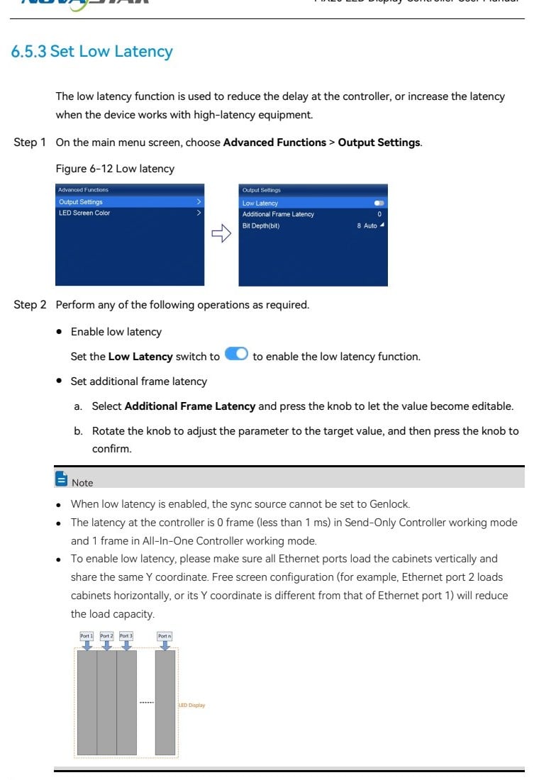
NovaStar recommends loading cabinets vertically on all Ethernet ports and setting every port’s starting Y coordinate to 0 when Low Latency is enabled. Horizontal loading or inconsistent Y coordinates can reduce output capacity. Measure the entire path after the change; the controller may be faster while another device still adds frames.
6. Tune Brightness, Gamma, Color, and Bit Depth
Perform color tuning only after timing and mapping are stable. Begin with a known neutral source, disable unplanned color transforms upstream, and confirm the LED modules are using the correct calibration data. Adjust brightness for the environment, then refine color temperature and gamma while viewing grayscale ramps, skin tones, saturated colors, and near-black detail.
Higher bit depth can improve gradients and low-level image quality, but it reduces port capacity. Choose 10-bit because the complete signal chain and content benefit from it, not because the option exists. Confirm the input, MX20, receiving cards, driver ICs, and LED modules all support the intended workflow.
After changing brightness, gamma, color temperature, or related screen parameters, use Screen Configuration > Save to RV Card. This writes the values to the receiving cards so the wall returns to the approved appearance after a restart. Store a photographed reference and measurement notes for future technicians.
7. Save MX20 Presets and Build a Recovery Workflow
The MX20 supports up to 128 presets, but more presets are not automatically safer. Use clear names tied to actual operating states, such as Primary 4K60, SDI Backup, Camera Low Latency, and Maintenance Test. Recall each preset during rehearsal and confirm that it changes only the intended source, layer, scaling, and output parameters.
Export the VMP project, receiving-card file, firmware record, network settings, and approved port map to two locations. If the controller uses a static IP, document the IP address, subnet mask, and gateway. The MX20 can export diagnostic logs to an NTFS- or FAT32-formatted USB drive, which is useful when an intermittent fault cannot be reproduced immediately.
Use factory reset carefully. NovaStar states that Reset All cannot be undone. Export known-good files and record the current setup before using it. A reset should be a controlled recovery step, not the first response to an unexplained blank screen.
8. Troubleshoot NovaStar MX20 Video Wall Problems in Order
A fixed diagnostic order prevents technicians from changing several variables at once. Start with power and physical links, then check the input, controller output, receiving-card topology, and cabinet configuration. Use the MX20’s internal test patterns to separate an upstream signal problem from a downstream LED system problem.
| Symptom | Check first | Corrective action |
|---|---|---|
| No image on the whole wall | Input lock, selected source, test pattern, output links | Verify the active input and timing. If the internal pattern displays, troubleshoot the source path. |
| Only one section is black | Port LED, cable order, first dark receiving card | Use Mapping, reseat or replace the link, and confirm the software route matches the physical chain. |
| Motion stutters or tears | Source frame rate, sync source, processing mode | Standardize the production timing, remove unnecessary scaling, and test Genlock or Low Latency as the design requires. |
| Image shifts after preset recall | Preset mode, layer coordinates, EDID state | Rebuild the preset from a verified input timing and confirm all layers remain inside the active canvas. |
| Fine gradients show banding | Source bit depth and full signal-chain support | Enable 10-bit only after recalculating port loads and verifying receiving-card compatibility. |
| Configuration disappears after restart | Receiving-card save state | Use Save to RV Card and verify the result with a controlled power cycle. |
If the issue persists, export logs and preserve the exact fault state before making large changes. Record the time, active input, preset, mode, firmware, and affected ports. For product selection or system-level questions, EagerLED’s NovaStar processor guide and LED video controller category provide useful context.
9. NovaStar MX20 Configuration Checklist
- Record MX20 firmware, VMP version, receiving-card model, cabinet resolution, and driver IC.
- Confirm the source raster, frame rate, color format, and bit depth before mapping.
- Select All-In-One or Send-Only mode according to processing and latency needs.
- Use Swift Layout only for a regular screen that meets NovaStar’s loading rules.
- Use VMP and Mapping for complex wiring, irregular canvases, and topology verification.
- Calculate every Ethernet port load for the actual bit depth and frame rate.
- Avoid narrow rectangular load areas under 128 pixels where possible.
- Choose either Genlock or Low Latency, then validate the complete timing chain.
- For Low Latency, load ports vertically and align their starting Y coordinates at 0.
- Tune brightness, gamma, and color after timing and mapping are stable.
- Save approved screen parameters to the receiving cards.
- Test all presets, backup paths, internal patterns, and power-cycle recovery before handover.
Keep this checklist with the VMP file and the physical port map. A repeatable handover is especially important for rental inventory, where the same MX20 may be rebuilt for a different wall and production format each week.
10. NovaStar MX20 Configuration FAQs
1.How many pixels can one NovaStar MX20 control?
The MX20 can load up to 3.9 million pixels in total, with a maximum output width or height of 4096 pixels. Actual capacity depends on frame rate, bit depth, receiving-card model, and load geometry, so confirm the final VMP calculation.
2.Should I use Swift Layout or VMP for MX20 configuration?
Use Swift Layout for a regular rectangular wall made from equal cabinets with a consistent wiring pattern. Use VMP for free wiring, mixed routes, curved or irregular screens, detailed load calculation, and more controlled commissioning.
3.Why does the MX20 video wall stutter even when the image is sharp?
Sharpness and motion smoothness are separate. Check the source frame rate, EDID, scaling stages, sync source, preset timing, and camera shutter. A 59.94/60 Hz mismatch or an unlocked production chain can cause visible cadence problems.
4.Can the NovaStar MX20 use Genlock and Low Latency together?
No. The MX20 manual states that Low Latency and Genlock cannot be used at the same time. Choose the function that fits the production design, then validate motion, delay, and output capacity across the complete system.
5.What port capacity should I use for 10-bit video?
At 10-bit and 60 Hz, NovaStar lists approximately 494,791 pixels per port with A10s Pro receiving cards and about 329,861 pixels with other Armor-series receiving cards. Leave headroom and verify the exact receiving-card and driver-IC combination.
6.How do I keep brightness and color settings after a restart?
After adjustment, select Screen Configuration > Save to RV Card. Then perform a controlled restart and confirm that brightness, gamma, color temperature, and calibration behavior return correctly.
7.What is the fastest way to locate a wrong cable or cabinet route?
Enable the MX20 Mapping function. The cabinets can show Ethernet port and receiving-card numbers, allowing you to compare the physical chain with the VMP topology and find the first incorrect connection.
11. Conclusion: Repeatable MX20 Setup for Smoother Shows
The best NovaStar MX20 configuration is not the one with the most advanced options enabled. It is the one that matches the source, wall geometry, receiving cards, port capacity, timing plan, and recovery procedure. Establish a verified baseline, set the correct EDID, map cabinets accurately, balance ports with real capacity limits, and choose sync and latency settings deliberately.
Finish by saving parameters to the receiving cards, testing presets and backups, and documenting the known-good state. That disciplined workflow makes video walls smoother during the show and makes faults much faster to diagnose when conditions change.
Technical references: NovaStar MX20 official download center and MX20 User Manual V1.5.1.