
EagerLED Academy
KyStar Control System Guide: S2 and S6 Senders, Gold Card Receivers and U-Series Processors
Nov
A KyStar control system is built from three kinds of parts: a sending device such as the S2 card or the S6 box, Gold Card receiving cards such as the G616 inside each cabinet, and, when you need switching or splicing, a U-series video processor in front of the senders. Size the sending side from the wall’s pixel count and width, pick receiving cards by connector count and driver IC, and add a processor only when the show needs multiple sources, windows or splicing.
This guide is for integrators and service technicians who are building, expanding or repairing a screen that runs on KyStar. It explains what each part of a KyStar control system does, compares the models in our store using the specifications on their product pages, works through a sizing example and covers the checks that matter when you replace a part.
Where a product page gives a figure, we quote it with its condition. Where it only links to a specification sheet, we say so rather than fill the gap with an estimate.
1. How a KyStar control system is built
Every synchronous LED screen needs a device that turns a video signal into network data, and a card in each cabinet that turns that data back into module signals. In a KyStar control system, the first job is done by a sending card or sending box, and the second by a Gold Card receiving card. A video processor is optional and sits in front of the sending device.
01. The sending side
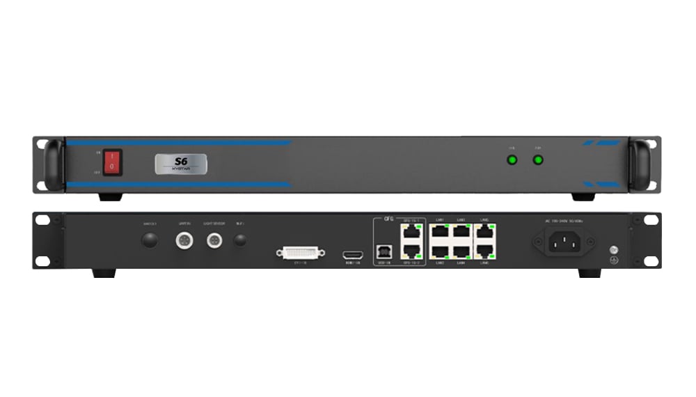
The sending device takes a DVI or HDMI signal from a computer, media player or video processor and splits the image across its Gigabit Ethernet ports. Each port feeds a chain of cabinets. The two sending devices we stock are the S2, a card that installs in a computer or sending box, and the S6, a standalone rack unit.
02. The receiving side
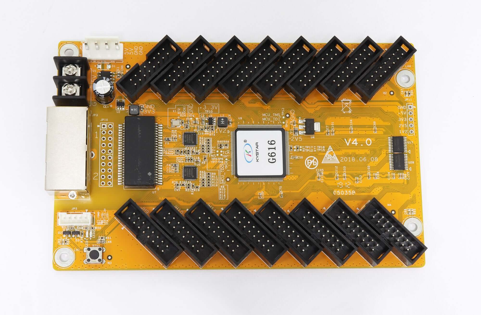
Each cabinet holds a Gold Card receiving card. It receives its part of the image from the network cable and drives the modules through its connectors. The G616 page lists 16 standard interfaces on a single card with 32 groups of RGB data, and support for general-purpose, PWM and dual-latch driver chips. The G612 page lists one-click readback of all profile information, one-click repair, point-by-point color and brightness correction, and real-time detection of network status and cable connection order.
03. The optional video processor
A U-series video processor handles switching, scaling and splicing before the signal reaches the sending device. You need one when the show uses several sources, picture-in-picture windows or a wall wider than a single sending device can handle. For a fixed sign showing one computer output, the processor is often unnecessary.
04. Software, calibration and control
A KyStar control system is set up from a computer connected to the sending device. The S6 page lists a square USB port and Gigabit Ethernet for connecting to the host computer, and cascade control of up to eight units over Gigabit. Calibration is part of the same chain: the S6 supports passive brightness and chroma correction with the KESD calibration system, which corrects each LED point independently of the video source, and the page states its fast correction data transmission is twice as fast as traditional methods. Plan who will hold the configuration and calibration files, because every replacement card in a KyStar control system will need them.
2. KyStar control system sending cards and boxes compared
The sending device sets the pixel capacity and width of each part of the wall, so it is the first part of a KyStar control system to size. The table compares the four sending products in our catalog.
| Model | Type | Inputs | Ethernet outputs | Load and size limits | Other listed features |
|---|---|---|---|---|---|
| S2 | Sending card | 1 DVI, 1 audio | 2 | 1.31 million pixels; max width 4,000, max height 2,000 | EDID management, one-click repair, network port backup, audio transmission, USB-CFG port |
| S6 | Sending box | 1 HDMI 1.3, 1 DVI; up to 2048 x 1152 at 60 Hz | 6 | 2.35 million pixels; max width 4,000 | Passive calibration, 3D, arbitrary cross-wiring, port redundancy, cascade up to 8 units |
| KS604 | Sending box chassis | 2 DVI | Depends on installed cards | Houses 4 small sending cards | Two 1-to-2 DVI splitters; copies up to 2.6 million pixels; 1.5U |
| KS606 | Sending box chassis | Depends on installed cards | Depends on installed cards | Houses 6 small sending cards | Independent power supply; 1.5U |
01. S2 sending card
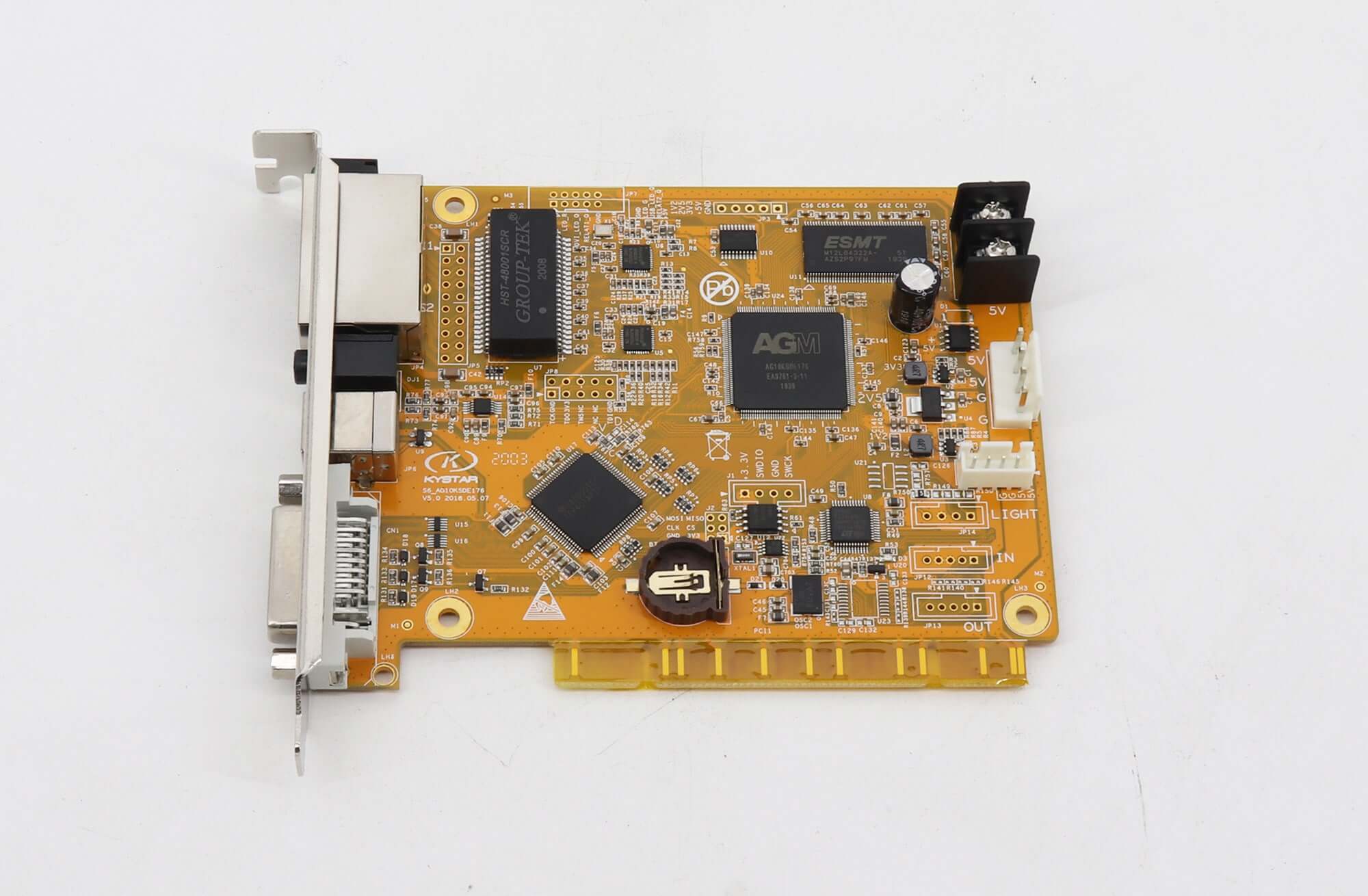
The S2 is the compact option. Its page lists one DVI input, an audio input, two Gigabit Ethernet outputs and a load of 1.31 million pixels, with a maximum width of 4,000 and height of 2,000 pixels. It suits small and medium screens, or larger screens split across several S2 cards in a sending box.
02. S6 sending box
The S6 adds HDMI input, six outputs and 2.35 million pixels. Its page lists a single-port load written as 65W, using the Chinese ten-thousand unit, which equals 650,000 pixels. It also lists arbitrary cross-wiring, where empty areas of an irregular screen do not use load capacity, and passive brightness and chroma calibration with the KESD calibration system. Up to eight S6 units can be cascaded and controlled together over Gigabit Ethernet.
03. KS604 and KS606 sending boxes
The KS604 and KS606 are chassis that hold several small sending cards with their own power supply, so a large screen’s sending cards sit in one 1.5U box instead of inside a computer. The KS604 holds four cards and includes two DVI splitters, each dividing one input into two. The KS606 holds six cards.
04. Which sending device to choose
For a single screen up to about 1.3 million pixels fed from a computer, an S2 card is the simplest choice for a KyStar control system. For a screen up to 2.35 million pixels that needs an HDMI input, a standalone box or cascade control, the S6 fits. For large screens that need several sending cards in one place, a KS604 or KS606 chassis keeps the cards, their power and the DVI distribution together in one rack unit. Whichever you choose, keep a spare sending device of the same model for live events.
3. U-series video processors
The U-series processors add source switching, windows and splicing in front of the senders in a KyStar control system. Two older models, the U1 and U1A, are listed as no longer in production on our pages, so new projects should start from the U2 or later.
| Model | Output capacity | Outputs and windows | Other listed features |
|---|---|---|---|
| U2 | Up to 2560 x 1536 at 60 Hz; user-defined output up to 2.6 million pixels | Two output ports, including a copy mode for two identical screens | Multi-unit synchronous cascade; synchronized audio and video transitions |
| U3 | User-defined output up to 2.6 million pixels; up to 2560 x 1536 at 60 Hz in mosaic mode | Two splicing outputs plus one monitoring output; three-image layout | 4K signal processing, luma key, multi-level input backup |
| U3 Pro | User-defined output up to 5.2 million pixels; up to 15,360 wide or 6,144 high | As U3 | As U3 |
| U4 | Up to 15,360 wide or 6,144 high, for example 15360 x 400 or 960 x 6144 | Six windows on one screen or six separate screens | DVI, HDMI, 2 VGA, 2 CVBS, SDI and an expansion slot; hot input backup |
| U6 | Up to 15,360 wide or 6,144 high | Four DVI outputs (from the product title); six windows | HDMI input; multi-window switching |
01. Choosing between the U2, U3 and U3 Pro
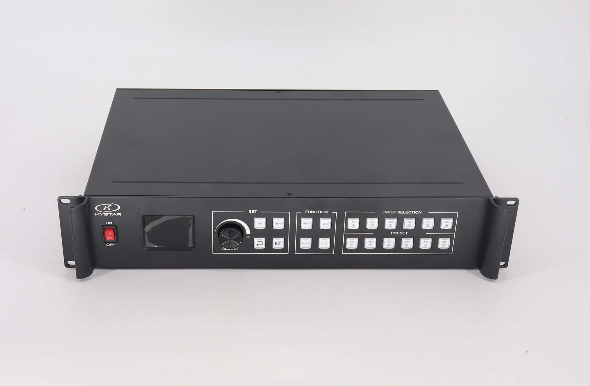
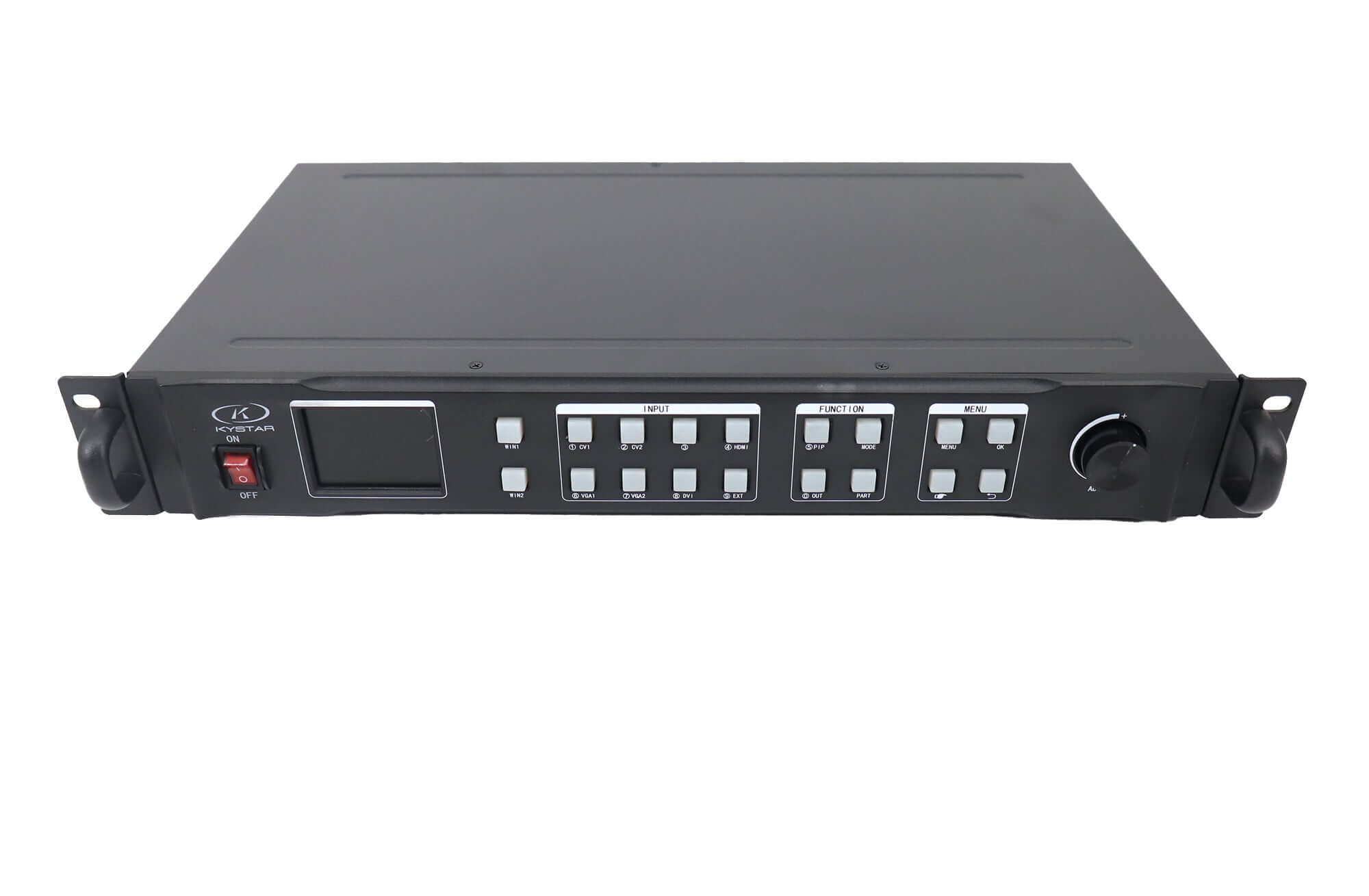
The U2 and U3 both list a user-defined output of up to 2.6 million pixels, which fits one sending box of the S6’s size. The U3 adds a monitoring output and a three-image layout for main and side screens. The U3 Pro doubles the user-defined output to 5.2 million pixels and allows outputs up to 15,360 pixels wide, so it can splice two or more sending boxes into one wide image.
02. When the U4 or U6 fits
The U4 and U6 suit multi-window work: their pages list six windows on one screen, or six separate screens on the U4, and output widths up to 15,360 pixels. The U4 has the broadest input set, including SDI, VGA and CVBS, which helps when a venue still uses older sources.
03. Backup and transitions on a live show
Live events need a plan for failure at every stage of a KyStar control system. On the processor side, the U3 page lists warm backup of multi-level input signals and more than ten transition effects, and the U4 page lists hot backup of input signals. On the sending side, the S2 page lists network port backup and the S6 page lists Ethernet port redundancy, which lets a second cable path take over if one fails. Using these features means reserving ports and inputs for backup when you size the system, not after it is installed.
4. Sizing a KyStar control system for your wall
Sizing a KyStar control system follows the same order every time: total pixels, width, port mapping, then processor. Getting the sending side right first avoids buying a processor that has nothing suitable to feed.
01. Check total pixels and width
Multiply the wall’s pixel width by its pixel height and compare it with the sending device’s load: 1.31 million for the S2 and 2.35 million for the S6. Then check the width separately. Both list a maximum width of 4,000 pixels, so a wall wider than that must be split across devices even if its total pixel count is small.
02. Map the Ethernet ports
At 650,000 pixels per port on the S6, divide the wall into port groups along whole cabinet rows or columns. The S6 page notes that arbitrary cross-wiring lets empty areas of an irregular shape not count against load, which helps with curved or stepped walls.
03. A worked example
Take a stage wall of 3,840 x 1,080 pixels, which is 4,147,200 pixels in total. That is above one S6’s 2.35 million pixels, so split it into two halves of 1,920 x 1,080 pixels. Each half has 2,073,600 pixels, below the S6 limit and well within its 4,000-pixel width. Each half needs at least four ports at 650,000 pixels, which fits the S6’s six. To show one continuous image across both halves, a processor with an output of at least 4.1 million pixels and 3,840 pixels of width is needed, so the U3 Pro, at 5.2 million pixels, fits on paper while the U3, at 2.6 million, does not. This KyStar control system example is illustrative; confirm the cabinet map and cabling for your own wall.
| Check | Limit to compare against | What to do if it is exceeded |
|---|---|---|
| Total pixels per sending device | S2: 1.31 million; S6: 2.35 million | Split the wall across more sending devices |
| Width per sending device | 4,000 pixels for the S2 and S6 | Split vertically into narrower sections |
| Pixels per Ethernet port | 650,000 on the S6 | Add ports by regrouping cabinets |
| Processor output | U2 and U3: 2.6 million; U3 Pro: 5.2 million | Choose the U3 Pro, U4 or U6, or cascade units |
| Cabinet connectors | G616: 16 interfaces, 32 RGB groups | Choose a card with enough connectors for the module cables |
04. Choose the receiving cards
Inside each cabinet of a KyStar control system, count the module cables and check the driver IC, just as you would with any brand. The G616 has 16 interfaces for up to 16 module cables and lists support for general-purpose, PWM and dual-latch chips. For a cabinet with fewer cables, the smaller Gold Card models may fit; check their specification sheets, since their pages do not list connector counts. Our LED hub card guide explains how to read module connectors if you are unsure what the cabinet uses.
5. Replacing parts in a KyStar control system
Replacing a part on an existing screen needs its own checks, because the new part has to match a configuration that is already running.
01. Use readback and repair functions
The G612 page lists one-click readback of all profile information and one-click repair, and the S2 page also lists one-click repair. Before replacing a card, read back and save the configuration from the working system, so the replacement can be loaded with the same settings.
02. Keep the chain in one system
Receiving cards are usually configured through the sending side’s software, so a KyStar control system should keep KyStar sending and receiving devices together. If you want to change brands on one side, plan to change the whole control chain and reconfigure the screen, rather than mixing a single card into an existing system.
03. Plan for discontinued models
The U1 page names the U1A as its alternative, but the U1A page states that it is also out of production. If your screen uses either, choose a current U-series model by output capacity and inputs, and budget time to rebuild the presets.
04. Note the camera-related features
The Gold Card pages describe an arbitrary multiplier technology intended to reduce scan lines when the screen is filmed with phones or cameras. If the screen is used for broadcast or streaming, keep this setting in mind when you configure replacement cards so they match the rest of the wall.
05. Keep a parts record
For every KyStar control system you install or maintain, keep a simple record: the sending device model, the receiving card model in each cabinet, the processor model, firmware versions where shown, and copies of the configuration and calibration files. When a part fails, this record turns a site visit into a quick order, because the replacement can be matched and prepared before anyone opens the screen.
Frequently asked questions
What is the difference between the KyStar S2 and S6?
The S2 is a sending card with one DVI input, two Ethernet outputs and a load of 1.31 million pixels. The S6 is a standalone box with HDMI and DVI inputs, six Ethernet outputs and a load of 2.35 million pixels. Both list a maximum width of 4,000 pixels.
What does “65W pixels” mean on the S6 page?
W is the Chinese ten-thousand unit, so 65W means 650,000 pixels per Ethernet port. The page’s overview gives the total load as 2.35 million pixels.
Does every KyStar control system need a video processor?
Only if the screen needs source switching, multiple windows or splicing across several sending devices. A screen fed by one computer output and one sending device can often run without one.
Can a KyStar receiving card work with another brand’s sending card?
Plan on keeping the control chain within one system. Receiving cards are usually configured through the sending side’s software, so mixing brands usually means reconfiguring the whole screen.
Which KyStar processor can splice a 4K-wide wall?
On paper, the U3 Pro, U4 and U6 list output widths up to 15,360 pixels, and the U3 Pro lists a user-defined output of 5.2 million pixels. Confirm the output layout and the sending devices behind each output before ordering.
Are the KyStar U1 and U1A still available?
No. Our pages list both as out of production. New projects should use the U2 or a later model.
Getting the right KyStar parts
You can compare full specifications on our product pages for the KyStar S6, Gold Card G616, U3 and U3 Pro and KS604 sending box, or browse the full KyStar range.
For a parts check on an existing KyStar control system, send us your system details: the wall resolution, current sending and receiving card models, the number of module cables per cabinet, input sources and a saved configuration file if you have one. Product videos are also available on the EagerLED YouTube channel.