
EagerLED Academy
MFN300 Placement: Where Does It Go in the LED Chain?
Nov
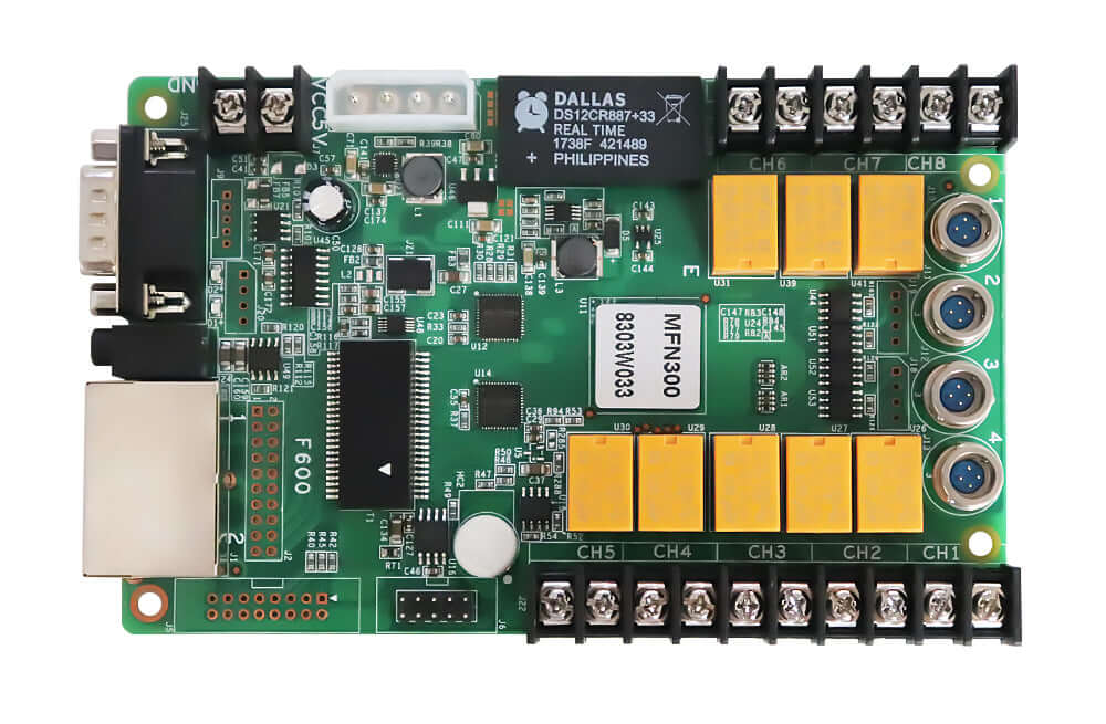
For MFN300 placement in a NovaStar receiving-card chain, the manufacturer’s V2.1.4 specification shows three positions: before the first receiving card, between two receiving cards, or after the last receiving card. Put the card where the technician can reach it and its peripherals, then check that the choice matches the actual Ethernet route and control configuration.
This guide is for an AV integrator adding an auxiliary function to a screen with a documented NovaStar chain. It covers the MFN300 card and the Ethernet arrangements shown in that specification. Confirm the instrument, control software and hardware identifiers for your project before approving the installation.
Compare the three MFN300 placement options
The NovaStar MFN300 product page identifies the card as a multifunction accessory. The V2.1.4 manufacturer specification describes connections ahead of the first receiver, between receivers, or at the end. These are locations in the signal route. Ask the electrician or integrator to show the matching physical enclosure and the way a technician will reach it.
Start with the existing drawing and highlight the exact controller output under review. For MFN300 placement before the first receiver, trace the controller’s outgoing connection to that receiver. The location may be near the controller or near the first cabinet, depending on where the cable runs and which space the project can use. Record both endpoints so the installers know which connection will change.
For MFN300 placement between two receivers, identify the upstream and downstream cabinets by their drawing labels. A note saying that the card goes in the middle of the wall leaves too much room for interpretation. A connection between two marked cabinet numbers can be traced before the work starts and verified after it ends.
After the last receiver may be a practical position when the far end of the run has usable service access and the required peripheral cables reach it. Confirm that the chosen cabinet really is the last receiver on that output. On a wall with several runs, the cabinet nearest an aisle may be at the end of the physical row and still be in the middle of a signal chain.
| Position | Record on the drawing | Check at the screen |
|---|---|---|
| Before first receiver | Controller output and first receiver ID | The installer can follow the original cable from both ends |
| Between receivers | Upstream and downstream receiver IDs | The proposed access point reaches both connections |
| After final receiver | Last receiver ID and accessory location | The cable route ends there, and the peripheral can reach it |
Mark the receiving-card route before ordering
Choose MFN300 placement from the sequence of devices and the service constraints together. For example, a wall might have two controller outputs, each feeding six cabinets. An accessory mounted next to cabinet six appears to be at the end of the first row. If the first output actually snakes through the cabinets and terminates at cabinet two, cabinet six is a different point in the chain. Draw arrows from the controller and label the cabinets in signal order.
Also show the peripheral route separately. The connections that carry the display link and the connections to auxiliary devices serve different purposes. If the project needs a light sensor, V2.1.4 describes sensor ports for light sensors and other supported peripherals. Confirm the exact sensor and cable arrangement for the order. Put the sensor location on the installation drawing so the cable length and service access can be reviewed before mounting the card.
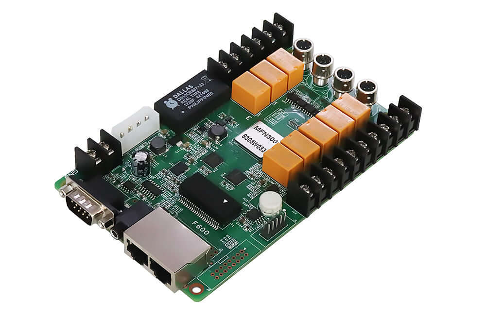
Keep the primary display path and the planned accessory function in separate blocks on the drawing. When several outputs use similar cabinet numbers, include the controller output identifier on both sides of the proposed installation point. If the site team uses a different cabinet naming system from the shop, include a short cross-reference. The LED display control systems guide explains the separate roles of senders and receivers.
Compare two accessible positions on paper
Suppose a service station is beside the first cabinet and the intended light sensor is closer to the last one. Annotate both options for MFN300 placement. Beside the first cabinet, the technician can reach the card from the service station, but the sensor route needs to cross the enclosure row. At the other end, the sensor route is shorter, but a removable panel may be obstructed by the mounting structure. Ask the installer to review both access points in the same visit.
Give each MFN300 placement option its own drawing note. Include what has been measured, what is still an estimate and who will verify any unresolved cable or access condition. Ask the cabinet supplier for a view with the proposed surrounding structure in place. A standalone cabinet drawing may omit an obstruction that appears after the cabinets are mounted together.
Specify the commissioning checks
Record the original signal path before work starts. In the acceptance plan, ask for an image check across the entire affected output and a separate check of the required accessory function. Compare the result with the baseline taken before the change. A working picture confirms part of the display test, while the sensor or other accessory function needs its own observed result.
For MFN300 placement between two receivers, include a check of cabinets on both sides of the installation point. For a unit positioned after the final receiver, include the last cabinet by its label and confirm that the accessory is visible through the intended control workflow. Document the configuration and the expected observation for that specific project before accepting it. Arrange the commissioning session so the people who can review the picture and the peripheral response are both available.
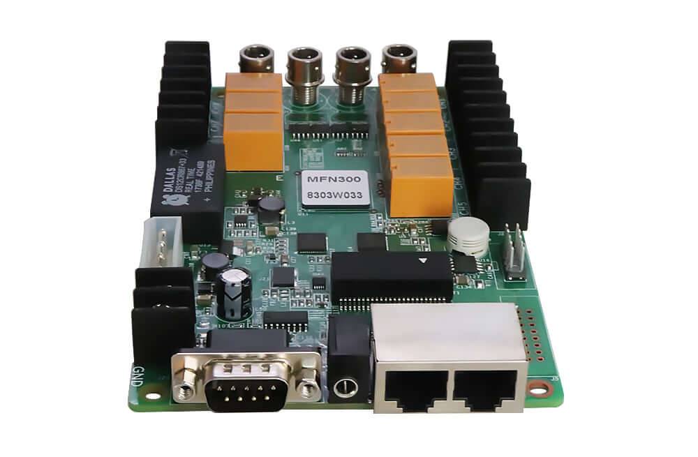
Hand over the final MFN300 placement with the updated route, cabinet IDs and peripheral identifiers. A labeled photo of the installed accessory gives the service team a quick way to find the enclosure without opening several cabinets. Include the approved diagram revision in the handover. When the field team changes the cable route, update the drawing before it becomes the maintenance reference.
Before issuing the final drawing, ask a colleague to trace the MFN300 placement from the marked controller output without asking the designer for directions. Have the colleague identify the proposed service panel, the sensor route and the exact point where the original chain changes. If any endpoint is unclear, resolve it in the drawing. Keep that review with the MFN300 placement decision in case the equipment arrives before the installation team is assigned.
Questions before finalizing the drawing
Does a convenient cabinet location establish sensor compatibility?
No. A reachable location helps service. Verify the sensor model, connection and supported configuration separately before ordering the peripheral.
Can the same routing note be used for the MFN300-B?
Check the specification for the model actually ordered. This page uses the MFN300 card specification. Similar names do not establish identical enclosure, connectors or supporting accessories.
What if the existing receiving-card route is undocumented?
Have the site team trace and label the relevant route first. Record the sending output, the sequence of cabinet identifiers and the final receiver. Then choose the accessory location using that record.
Send the route to EagerLED for a review
Share the proposed MFN300 placement, the controller and receiving-card model numbers, and the accessory function you need. Mark the upstream and downstream connections on a simple diagram and identify the cabinet location. Contact EagerLED about your MFN300 connection plan with the drawing and the peripheral model for review.