
EagerLED Academy
LED Hub Card Guide: How to Match HUB75E, HUB08, HUB12 and HUB73 to Your Modules

Nov
An LED hub card is the small adapter board that sits between a receiving card and the ribbon cables of the LED modules. It takes the dense pin header of the receiving card and breaks it out into a row of module connectors such as HUB75E, HUB08, HUB12 or HUB73. The right LED hub card is decided by the pin definition printed on the module input, not by pixel pitch, cabinet size or the brand of the controller.
This guide is written for service technicians and integrators who need to replace or source a hub card for an existing cabinet. It explains what each common interface carries, how to read a module header before you order, which receiving cards remove the need for a separate board, and which details to send with a quotation request so the spare fits the first time.
All pin definitions below come from the interface definitions published on our own product pages. Where a connector name is used loosely in the market, we point out what to check on the board itself, because two cards with the same pin count can still be wired differently.
1. What an LED hub card does in the signal path
In a synchronous LED display, video data travels from the sending device to the receiving card over Ethernet cable. The receiving card turns that data into the parallel signals a module expects: color data lines, row address lines, a clock (CLK), a latch (LAT) and an output enable (OE). An LED hub card carries those signals from the receiving card to each module cable and buffers them along the way.
01. The chain from controller to module
The usual order inside a cabinet is: sending card or video controller, network cable, receiving card, LED hub card, flat ribbon cable, module. Many receiving cards use one or two high-density pin headers instead of module connectors. The LED hub card plugs onto those headers and gives you four, six, eight or more standard outputs, depending on the design. The hub boards pictured in this guide carry line driver chips between the input header and the output connectors, which is why they are more than simple pass-through adapters.
The LED hub card does not decide refresh rate, grayscale or scan mode. Those settings come from the receiving card configuration and the module driver IC. The hub card only has to present the right signal on the right pin. That is also why a wrong card usually produces obvious symptoms, such as scrambled rows, missing colors or a module that stays dark, rather than a subtle change in image quality.
02. When you can skip the separate board
Some receiving cards already carry standard module connectors on the board. In that case no separate LED hub card is needed, and the module cables plug straight into the receiving card. The product description of the NovaStar MRV328 receiving card on our store states this directly: it integrates eight standard HUB75 connectors, which makes the HUB board unnecessary.

Cards like this simplify a cabinet, but they only suit modules that use the onboard connector type. If your modules use HUB08, HUB12 or a 20-pin outdoor format, you still need a receiving card with a pin header plus the matching LED hub card. Section 4 compares the onboard options we stock.
2. Common hub interfaces and what each one carries
Hub interface names describe a pin layout, not a quality level. The number after “HUB” is a naming convention used across the industry, and it does not always match the pin count. HUB75 and HUB75E use a 16-pin header, while HUB73 and HUB34 use 20 pins. The safest way to compare them is by what the pins carry.
01. HUB75 and HUB75E for full-color modules
HUB75 is the most common connector on full-color indoor and outdoor modules. It is a 16-pin (2 x 8) header that carries two groups of red, green and blue data (R1, G1, B1 and R2, G2, B2), four row address lines (A, B, C, D), plus CLK, LAT, OE and ground. Four address lines allow up to 16 row combinations, which covers modules up to 1/16 scan.
HUB75E keeps the same 16-pin header and the same data lines but adds a fifth address line, E. On the HUB75E card pictured below, the silkscreen places E on pin 8, which is a ground pin in the plain HUB75 layout. Five address lines cover modules up to 1/32 scan, which is common on fine-pitch indoor modules. Our HUB75E LED wall hub card is listed for traditional indoor modules and for P10, P7.62, P6, P5, P4, P3 and P2.5 modules.

Because the pin 8 assignment differs, do not assume a HUB75 and a HUB75E board are interchangeable in every cabinet. Check the scan mode in the existing receiving card configuration and the module silkscreen before you mix them.
02. HUB08 and HUB12 for single- and dual-color signs
HUB08 and HUB12 are mostly found on single-color and dual-color (red and green) modules used for text signs, tickers and price boards. Both use 16 pins, but they carry less color data than HUB75.
- HUB08: the published definition on our HUB08 card is 1 GND, 2 A, 3 GND, 4 B, 5 GND, 6 C, 7 OE, 8 D, 9 RD1, 10 GD1, 11 RD2, 12 GD2, 13 GND, 14 LAT, 15 GND, 16 CLK. That gives two red and two green data lines with four address lines.
- HUB12 (HUB12A): the published definition is 1 OE, 2 A, 3 GND, 4 B, 5 GND, 6 C, 7 GND, 8 CLK, 9 GND, 10 LAT, 11 GND, 12 RD, 13 GND, 14 GD, 15 GND, 16 D. That is one red and one green data line with four address lines.

Even though HUB08 and HUB12 share a 16-pin header, their pin orders are completely different. A HUB12 module on a HUB08 card will receive clock on the wrong pin and will not display correctly. Large single-color signs often use boards with many HUB12 outputs, such as the 16-output board below, so one receiving card can drive a long row of modules.

03. Multi-group formats: HUB73, HUB34, HUB16 and others
Some outdoor full-color modules accept more than two RGB groups per cable, so they use 20-pin or larger headers. These formats are less standardized, and the same 20-pin size hides very different layouts. The definitions below are taken from our product pages:
- HUB73: 20 pins carrying four RGB groups (RD1 to BD4), three address lines (A, B, C), CLK, LAT, OE and ground.
- HUB34: 20 pins carrying three RGB groups (R1 to B3), four address lines (A, B, C, D), CLK, LAT, OE and several grounds.
- HUB16: 20 pins carrying five RGB groups, with CLK, LAT, OE and ground and no address pins in its published definition.
- HUB94N: 20 pins carrying four RGB groups, each followed by a ground, then CLK, LAT, OE and ground, also with no address pins listed.
- HUB97: a 10-pin header with one RGB group and two address lines (A, B).
- HUB122: a 26-pin header with eight red, four green and four blue data lines and two address lines (A, B).

The table below puts these formats side by side. Use it as a first filter, then confirm the exact pin order on the module.
| Interface | Header | Color data per port | Row address pins | Typical modules |
|---|---|---|---|---|
| HUB75 | 16-pin | 2 RGB groups | A, B, C, D | Full-color modules up to 1/16 scan |
| HUB75E | 16-pin | 2 RGB groups | A, B, C, D, E (E on pin 8) | Full-color modules up to 1/32 scan, many fine-pitch indoor types |
| HUB08 | 16-pin | 2 red + 2 green lines | A, B, C, D | Single- and dual-color sign modules |
| HUB12 / HUB12A | 16-pin | 1 red + 1 green line | A, B, C, D | Single- and dual-color sign modules |
| HUB73 | 20-pin | 4 RGB groups | A, B, C | Outdoor full-color modules with 4-group input |
| HUB34 | 20-pin | 3 RGB groups | A, B, C, D | Outdoor full-color modules with 3-group input |
| HUB16 | 20-pin | 5 RGB groups | None listed | Modules wired for 5-group input without header address lines |
| HUB94N | 20-pin | 4 RGB groups | None listed | Modules wired for 4-group input without header address lines |
| HUB97 | 10-pin | 1 RGB group | A, B | Small full-color modules with a 10-pin input |
| HUB122 | 26-pin | 8 red, 4 green, 4 blue lines | A, B | Modules with a 26-pin input |
3. How to identify the LED hub card your modules need
The fastest way to order the right LED hub card is to read three things: the module input header, the old hub card, and the receiving card header. Most mistakes come from relying on only one of them, or from going by the module’s pixel pitch.
01. Read the module input silkscreen
Turn the module over and find the input connector, usually marked IN or with an arrow pointing into the module. Most module boards print the signal name next to each pin. Write the labels down in pin order, starting from pin 1, which is normally marked with a triangle, a square pad or a “1”. Then compare the list with Table 1 and with the interface definition on the product page. If the labels read R1, G1, B1, GND, R2, G2, B2, E, A, B, C, D, CLK, LAT, OE, GND, you are looking at HUB75E.
02. Photograph the old hub card and cable
If the cabinet already has a working or failed LED hub card, take clear photos of both sides. The board name and version are often printed on the top layer, as on the HUB08 Ver2.0, HUB73 and QP-HUB34 boards in this guide. Also note the number of outputs in use, the length of the module ribbon cables and whether the board is mounted on the receiving card or connected by a separate flat cable.
03. Match the receiving card side
The input side of the LED hub card must fit the receiving card header in both pin count and signal order. Hub cards are designed for a particular family of receiving card headers, so the same “HUB75” name can appear on boards with different input sides. Record the receiving card model and, if possible, its header labels before you order. If you plan to change the receiving card at the same time, choose the card first and then the matching LED hub card.
| What to check | Where to find it | Why it matters |
|---|---|---|
| Module input pin labels and pin 1 position | Silkscreen beside the module IN connector | Decides the output format: HUB75, HUB75E, HUB08, HUB12, HUB73 and so on |
| Pin count of the module connector | Count the pins: 10, 16, 20 or 26 | Rules out formats quickly, but never confirms one on its own |
| Scan mode of the module | Module label or the existing receiving card configuration file | 1/32 scan needs the E address line, so HUB75 is not enough |
| Board name and version on the old card | Printed text on the hub card PCB | Finds a direct replacement with the same input and output layout |
| Receiving card model and header | Label on the receiving card | The hub card input must match the receiving card header |
| Number of outputs in use | Count the connected ribbon cables | Avoids buying a board with too few ports for the cabinet |
| Mounting position and spacing | Measure screw holes and headroom in the cabinet | Some boards stack on the receiving card, others need cable links |
If any label is unreadable, send us clear photos of the module back, the old hub card and the receiving card. Matching from photos is usually faster than guessing from a part name, and it avoids a second shipment.
4. When the receiving card already has the connectors
For new full-color cabinets, a receiving card with built-in HUB75 or HUB75E connectors removes one board and one set of connections. Fewer connections mean fewer places for a loose header or a bent pin. This option only applies when the modules use the same connector as the receiving card.
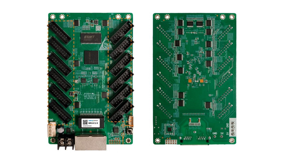
The table below summarizes three receiving cards from our catalog that carry module connectors on the board. The figures are taken from the product pages, which cite the manufacturer specification versions noted there.
| Receiving card | Onboard connectors | Parallel RGB data | Published pixel load |
|---|---|---|---|
| NovaStar MRV328 | 8 x HUB75 | Not stated on our page | Up to 256 x 256 pixels |
| NovaStar MRV408-S | 8 x HUB75E | Up to 16 groups | Up to 512 x 512 pixels at 60 Hz with PWM driver ICs and an 8-bit source; 512 x 384 with common driver ICs |
| NovaStar MRV412-S | 12 x HUB75E | Up to 24 groups | Up to 512 x 512 pixels at 60 Hz with PWM driver ICs and an 8-bit source; 512 x 384 with common driver ICs |
Each HUB75E connector carries two RGB groups, so the eight connectors of the MRV408-S give 16 groups and the twelve connectors of the MRV412-S give 24 groups. When you choose between them, check both the pixel load and the number of module cables in the cabinet. A cabinet with nine or more module cables will not fit on an eight-connector card, even if the total pixel count is within the published load.
A separate LED hub card is still the right choice when the modules use HUB08, HUB12 or a 20-pin format, when you need to keep an existing receiving card that has only pin headers, or when the cabinet layout places the connectors far from where the receiving card is mounted.
5. Replacement mistakes that stop a cabinet from working
Most failed replacements we see come from a handful of avoidable errors. Checking them before power-on saves time on site.
01. Choosing by pin count alone
HUB73 and HUB34 both use 20 pins, but HUB73 carries four RGB groups with three address lines, while HUB34 carries three RGB groups with four address lines. HUB08 and HUB12 both use 16 pins with different orders. A connector that fits physically is not proof of a match. Always compare the full pin order.
02. Mixing HUB75 and HUB75E without checking the scan mode
A 1/32 scan module needs the E address line. On a plain HUB75 board, the pin that carries E is a ground, so the lower half of each scan group will not light correctly. The reverse case, a HUB75E board on HUB75 modules, depends on how the modules handle pin 8. Confirm with the module silkscreen and the existing configuration file rather than assuming backward compatibility.
03. Reversing the ribbon cable or the board
Ribbon cables have a keyed plug and a colored edge that marks pin 1. If a cable is turned around or the LED hub card sits one row off on the receiving card header, the module will show scrambled or missing rows. Check the pin 1 marks on both the LED hub card and the module before you close the cabinet.
04. Ignoring the configuration file
A new LED hub card of the correct type will not fix a display that has lost its receiving card configuration. Keep a copy of the working configuration file and confirm it is loaded after the swap. If the image is wrong after a hardware change, check the configuration before ordering a second board.
05. Replacing several parts at once
When a cabinet goes dark, replace one part at a time: first the ribbon cable, then the LED hub card, then the receiving card. Swapping all three together hides which part failed and makes the next repair slower.
Frequently asked questions
Is HUB75 the same as HUB75E?
No. Both use a 16-pin header with two RGB groups, but HUB75E adds a fifth row address line, E, on pin 8. HUB75 uses that pin as ground. HUB75E is needed for modules that run at 1/32 scan.
Can any 20-pin hub board replace another 20-pin board?
No. On our product pages, HUB73, HUB34, HUB16 and HUB94N all use 20 pins, yet they carry three, four or five RGB groups and different address lines. Order by the published pin definition, not by the pin count.
Does an LED hub card change brightness or refresh rate?
No. Brightness, refresh rate and scan settings come from the receiving card configuration and the module driver IC. The hub board only routes and buffers the signals, so a wrong board shows up as scrambled rows or missing colors rather than a change in refresh.
What should I send to get a matching replacement?
Send clear photos of the module input header, both sides of the old board and the receiving card label, plus the number of outputs in use and the module scan mode if you know it. These details are usually enough to confirm the interface without a site visit.
Do I need a hub board if my receiving card has onboard HUB75E connectors?
Not for HUB75E modules. Cards such as the MRV408-S and MRV412-S connect to HUB75E modules directly. You only need a separate board if your modules use a different format, such as HUB08, HUB12 or a 20-pin layout.
Ordering the right hub card for your cabinet
Start from the module input header, confirm the pin order against the definitions above, and then match the receiving card side. Our store lists boards by interface, including the HUB75E LED wall hub card, the HUB08 hub card, the HUB73 hub card and the HUB34 data transport board. Other formats are grouped under other LED display parts. If you are rebuilding a full-color cabinet, compare these with receiving cards that carry onboard connectors, such as the NovaStar MRV412-S, in our LED receiving card range.
If you are not sure which LED hub card fits, contact our team with your module and receiving card details. Include photos of the module input header, the old board and the receiving card label, the number of outputs in use and the quantity you need. You can also see installation and maintenance clips on the EagerLED factory YouTube channel.