
EagerLED Academy
LVP615S USB Control: Can the USB Port Carry Your Video?
Nov
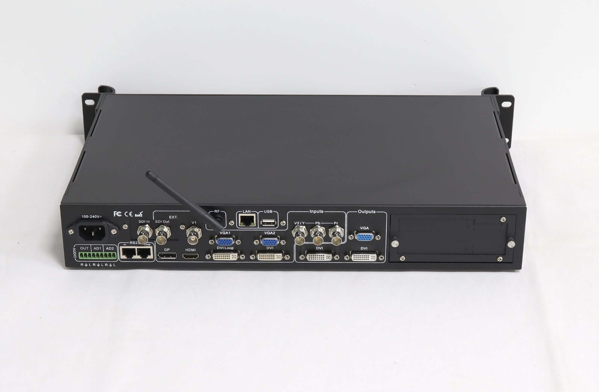
LVP615S USB control is a way for a computer to communicate with the processor. The linked LVP615S V1.0 manual identifies USB as a communication port, separately from the video inputs. Do not plan to send a laptop picture through that socket or assume it can play files from a USB flash drive. A supported video input still needs its own source connection.
This explanation is for an AV integrator preparing the source and control connections for an LVP615S order. It separates the two jobs, gives a hypothetical laptop setup and shows what to record before commissioning. Match the manual and rear-panel labels to the supplied hardware revision.
What LVP615S USB control actually does
The manual puts USB under the other communication ports, while its video-input section lists connections such as HDMI, DVI, DisplayPort, VGA and the extended SDI input. In the remote-control chapter, USB is described as an alternative when the computer does not have an RS232 port. These descriptions establish the documented role of the socket.
Use LVP615S USB control for the processor’s control connection, with the appropriate software and cable confirmed for the unit. It does not turn that connection into a video input. A successful software connection and a visible laptop image therefore need separate checks; passing either one does not establish that the other path works.
The LVP615S product page links to the LVP615S V1.0 user manual. The relevant sections are 3.2 for port descriptions and 7.1.1 for RS232 and USB. Use the document version as part of the connection record, rather than relying on a family name alone.
Draw the control and video paths separately
Start with what each cable must accomplish. One path carries the source picture into the processor. Another lets the operator communicate with it. The processor’s output then continues toward the LED sending equipment. Writing these roles beside the cable lines makes an omitted connection easier to find before installation.
| Required job | Record before installation | Acceptance observation |
|---|---|---|
| Display the laptop picture | Source output, selected processor video input and agreed signal format | The intended source is recognized and its test image is visible |
| Control the processor from a computer | Control method, matching software, cable and selected device | The software reports a successful connection to the intended unit |
| Send the processed picture onward | Processor output and the specified LED sending equipment | The approved test image reaches the intended display area |
The table is a suggested acceptance record, not a report of an EagerLED installation. Complete its fields with the project’s actual hardware. For LVP615S USB control, the control row must identify the intended processor; a computer seeing a connected device is not, by itself, proof that the complete display chain is ready.
Also distinguish the processor’s LAN control interface from the outputs of LED sending equipment. A connector’s shape does not establish its job. Follow the labels and the model-specific connection diagram instead of moving a cable between similar-looking sockets to see what happens.
Example: one laptop, two different connections
Consider a hypothetical setup in which a laptop provides an HDMI source and also runs the processor control software. The video connection goes from the laptop’s suitable video output to the LVP615S HDMI input. The separate control connection uses the method agreed for the supplied unit. The laptop’s ability to support both roles must be confirmed.
With LVP615S USB control selected, connecting the control cable alone does not complete that example. The processor still needs the HDMI source connection. Conversely, a visible HDMI image does not prove the computer can communicate with the processor software. Record the two observations separately when checking the setup.
If the laptop provides only USB-C connectors, identify what each laptop port supports and specify the required video-output solution. The word USB in the laptop specification does not prove that the processor’s USB communication socket accepts the laptop’s picture. Confirm the complete source-to-input arrangement before purchasing adapters.
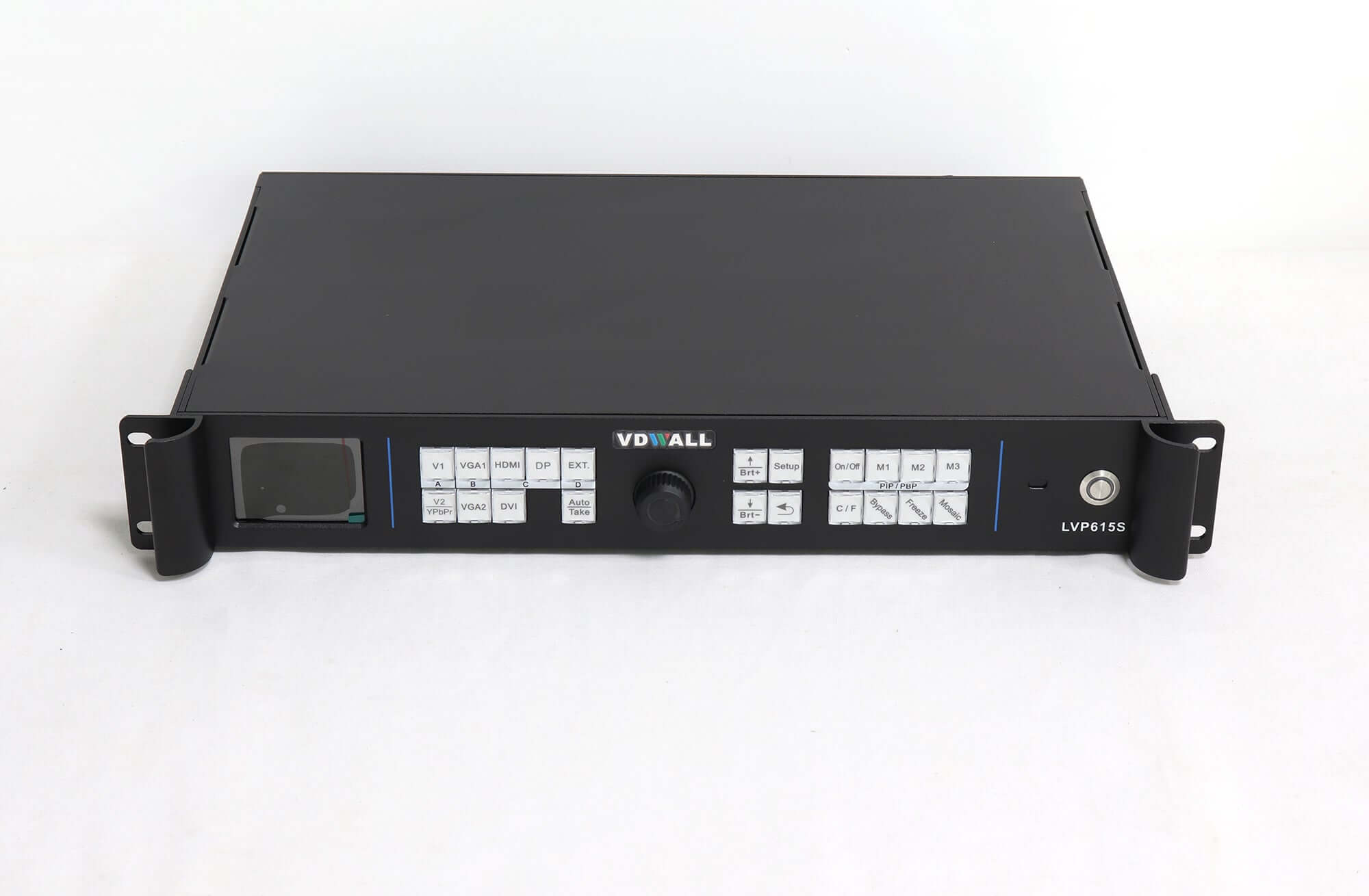
Use an agreed test image from the intended source, then confirm that the chosen input is selected. A picture from a different connected source can conceal a missing laptop connection. Note the source name and selected input on the test record so that the observation can be repeated.
Check LVP615S USB control without changing the screen map
The V1.0 manual’s PC-software instructions describe selecting a serial or network connection method. For serial communication, they call for the correct COM port and a device ID matching the processor. Those identifiers belong to communication setup; they should not be confused with the screen’s pixel dimensions or receiving-card mapping.
Before trying LVP615S USB control on a working installation, record the existing configuration and arrange a suitable maintenance window. Ask the supplier for the matching software, cable requirements and instructions for that hardware revision. This article does not establish that a particular driver or software release supports every current computer operating system.
If the application cannot connect, report the connection method, software version, computer operating system, device identifier and exact message. Do not change output resolution, reset the processor or rewrite the LED screen configuration merely to test a communication problem. Those actions address different settings and can interrupt an otherwise working picture.
When LVP615S USB control connects successfully, start with reading the displayed status and confirming the intended unit. Carry out any operational test only within the approved commissioning procedure. A software connection should be recorded as communication established, without implying that all sources, outputs and screen areas have passed their own tests.
Make the connection record useful to the next operator
Label the video and control cables by function at both ends. Keep a rear-panel photograph with the exact model, manual version and approved source format. If several processors are present, the record should let the next operator identify the correct unit without guessing from the position of a cable in the rack.
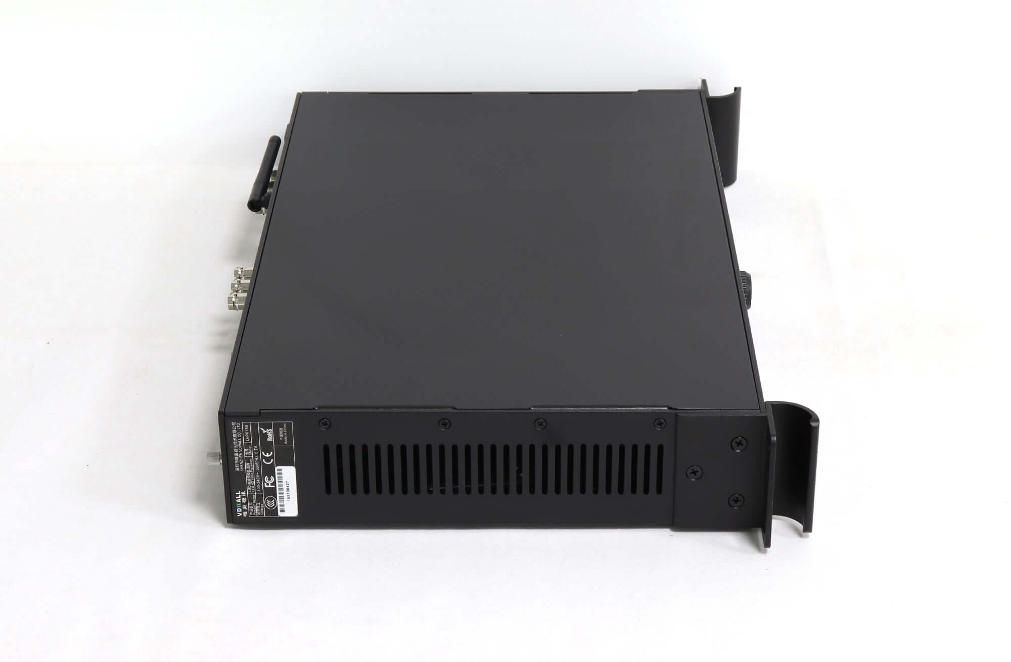
Keep the LVP615S USB control procedure alongside the video-path drawing. If a replacement computer changes the control setup, update the software and cable record. If the source output changes, review the video path independently. This division helps the support team understand which part of the system actually changed.
Questions before ordering the cables
Does a USB socket prove the processor plays files from a flash drive?
No. The cited LVP615S manual documents USB communication. It does not establish flash-drive media playback for this model. If standalone playback is required, put that requirement in the quotation and ask for a model-specific confirmation.
Does the order automatically include the required USB cable?
Confirm the cable and accessories in the actual quotation. A manual’s example connection does not prove what is included in an individual shipment, and the manual notes that supplied accessories can vary.
Can a different LVP615-family model use the same procedure?
Do not assume it. Confirm the complete model suffix, rear-panel labels and matching manual. Similar product names do not establish identical ports, playback functions or software requirements.
Confirm the source and control arrangement
Ask EagerLED to confirm your LVP615S USB control arrangement with the source device, operating system, intended video input and processor revision. Include any standalone-playback requirement before ordering. For a different signal path, review the LED video processor category and request confirmation against the selected model’s own documentation.