
EagerLED Academy
What Belongs in a Receiving Card Backup for a NovaStar MRV328?
Nov
A receiving card backup for a NovaStar MRV328 should connect the saved configuration to a specific physical cabinet. Keep the readback file, the installed hardware and software versions, a cabinet location map, and photographs of the module connections. Identify any firmware and calibration records separately. A folder labeled only “screen settings” gives the next technician no reliable way to choose the right file at a mixed installation.
This matters when a cabinet goes dark and the original card can no longer be read. The useful work happens while the sign is still healthy. A service manager can collect most of the identifying information without interrupting a display, then arrange a maintenance window with the operator for any software work that might affect the running system.
Give each receiving card backup a physical address
Choose a cabinet numbering convention that can be understood from either side of the wall. For instance, write “row two, column three, viewed from the audience” and add a photograph with that cabinet marked. A technician working behind the sign sees the columns in reverse. A label such as “left card” can lead two people to different cabinets even when both are looking at the correct screen.
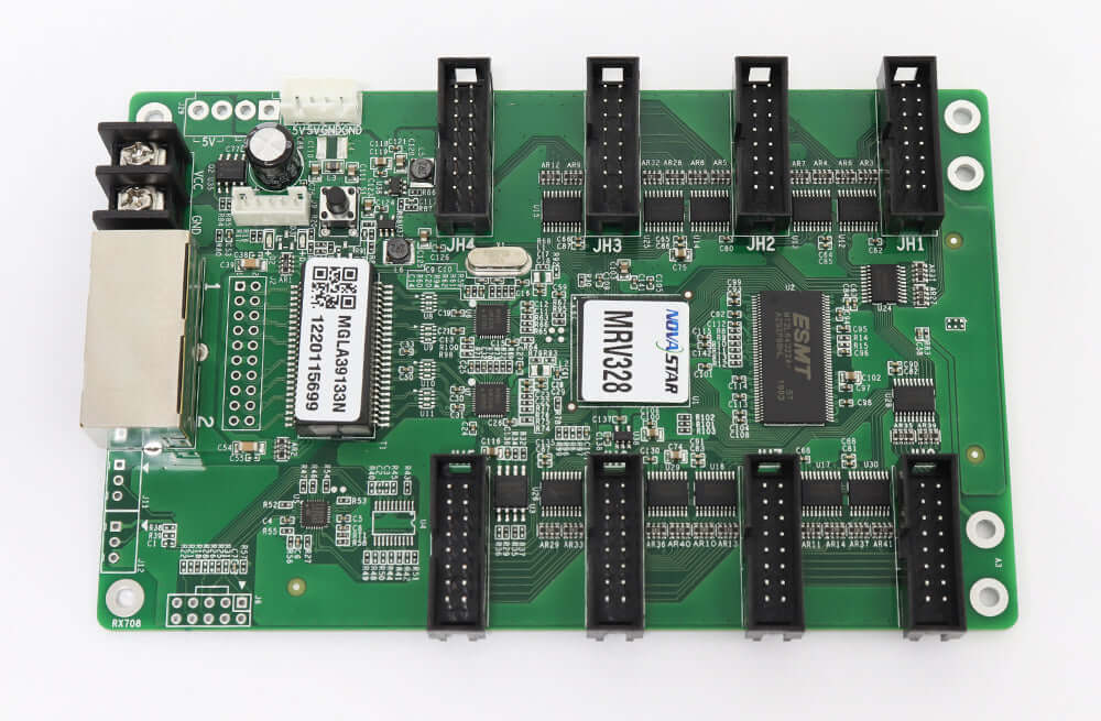
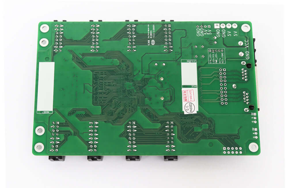
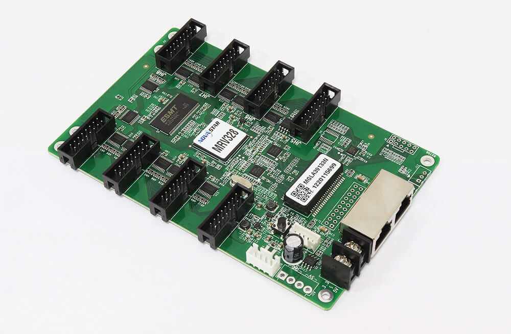
Identify what sits behind that cabinet door. Record the receiving card model, any legible board revision, the module markings and the position of each used ribbon connector. The MRV328 product reference describes eight integrated HUB75 connectors. Count the populated positions on your board. A clear photograph that includes a recognizable board edge makes it possible to orient a second photo after a cable has been removed.
Separate the configuration, firmware and cabinet map
The MRV328 V1.0.0 reference describes configuration parameter and firmware readback using NovaLCT V5.0.0 or later. Record the exact NovaLCT version available at the site and the identity of the connected control system. Ask the operator to identify a known working cabinet and confirm the target before reading from it. A readback from the wrong cabinet can produce a perfectly plausible file for a different module layout.
For each file, write down what was read and from where. The configuration describes how the card drives its attached modules. Firmware is software running on the card. A screen connection map identifies how receiving cards and cabinets relate to the overall image. Keep all three records under the site name and preserve their individual descriptions. Opening a receiving card backup months later should reveal whether the technician has an actual firmware file, a version number or just an unreadable photo of a label.
If the wall has been calibrated, ask whoever maintains it how calibration data is held and what approved recovery material exists for that cabinet. Note whether it was available and who can identify the correct copy. The manufacturer’s MRV328 specification hosted by EagerLED documents calibration support. That feature alone cannot establish which data a particular installer saved for a particular wall.
Decide whether a neighboring cabinet is a valid reference
A neighboring cabinet is a candidate for comparison when a failed card cannot respond. Before treating its receiving card backup as representative, compare its module markings, driven pixel area, ribbon connections and role in the cabinet map. Signs that were expanded or repaired at different times may contain different module batches behind identical doors. Where the histories differ, keep the cabinet records separate until the installer confirms which settings may be shared.
For example, imagine a service drawing showing full-width cabinets through the center of a sign and a narrower end section. The neighboring card might use the same connectors and still drive a different width. If the end card fails, a file from a center cabinet only tells you how the center is configured. Put the two dimensions side by side on the service ticket and identify the missing end-section data explicitly. This gives the supplier a better starting point than a file renamed after the failed unit.
Organize the receiving card backup for the next technician
| Record | Include in the folder | Useful cross-check |
|---|---|---|
| Physical identity | Cabinet address, viewpoint, model and board photos | Match the marked door to the wall drawing |
| Configuration | Original readback, date and software version | Identify the card from which it was read |
| Firmware | Observed version and any separate retrieved file | Distinguish available file from version-only record |
| Visual baseline | Approved test pattern and wall photo | Use the same pattern at handover |
Add an index sheet to the receiving card backup that lists the actual filenames. For a wall that was serviced twice, mark which visit produced the last known working configuration and retain the original copy from the earlier visit. If a supplier sends a proposed file, store it separately until the responsible technician has identified its intended board and module combination. A date-stamped folder is useful only if the person opening it can tell what was observed on site and what was proposed later.
Try handing the receiving card backup to a colleague who did not attend the visit. Ask them to locate the cabinet on the drawing, identify its module layout and name the file that came from its working card. If they have to phone the original installer to understand which end of the sign the folder describes, fix the labels while the equipment is still available. This small check catches a different class of problem than opening the file on the same laptop that created it.
Define what a successful swap will look like
Agree on a visual baseline before the maintenance window. A cabinet identifier across a test image can reveal an incorrect map. A border crossing a cabinet seam can show whether an edge is missing or repeated. Red, green and blue patches give the operator an easy way to describe a channel issue. A neutral field across neighboring cabinets can help reveal a visible mismatch for further investigation. Record the pattern and the conditions in which the comparison was made.
The technician responsible for the change should confirm the proposed card, software and approved files before writing to hardware. Keep the original receiving card backup intact during that process. After a controlled swap, have the operator compare the serviced area with the saved baseline and sign off the actual result. If the cabinet displays its content in the right position but looks different from its neighbors, record that observation separately from the mapping result. It points the next person toward a different part of the service record.
Questions that come up during a repair
What if the old card has already failed?
Start with the latest identified receiving card backup and the commissioning records. If no matching file exists, label the file from a healthy cabinet with its true origin. Send both cabinets’ details before asking whether that file is suitable for recovery.
Should a purchasing team send every file in the service folder?
Begin with the card identity, cabinet pixel dimensions, module details, software and firmware versions, and the symptom. State which files are available. The service contact can then request the particular item needed without having to sort through an entire site’s commissioning archive.
Can a product photograph identify where a ribbon cable belonged?
A product image can identify the board family and help orient the connectors. Only a site photograph, an installation drawing or another verified record can establish which ribbons were fitted to specific positions in that cabinet.
Give the supplier enough detail to evaluate the spare
When requesting a replacement, include the cabinet address, identified hardware, module wiring and a summary of your receiving card backup. Specify whether the original card still communicates and whether you have a comparable working cabinet at the same site. Contact EagerLED with the installed-card details so the replacement discussion starts with the equipment and files available for the repair.