
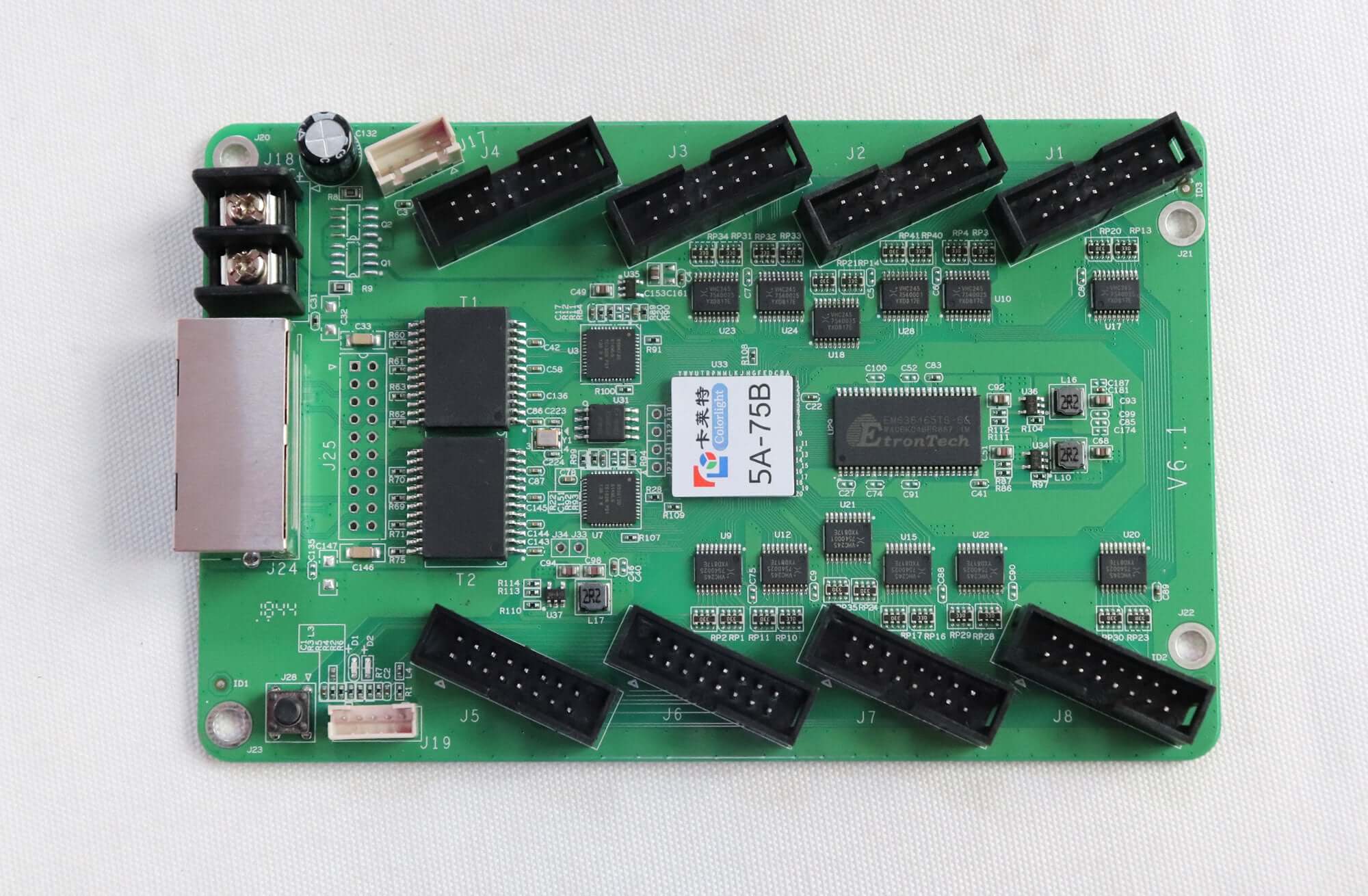

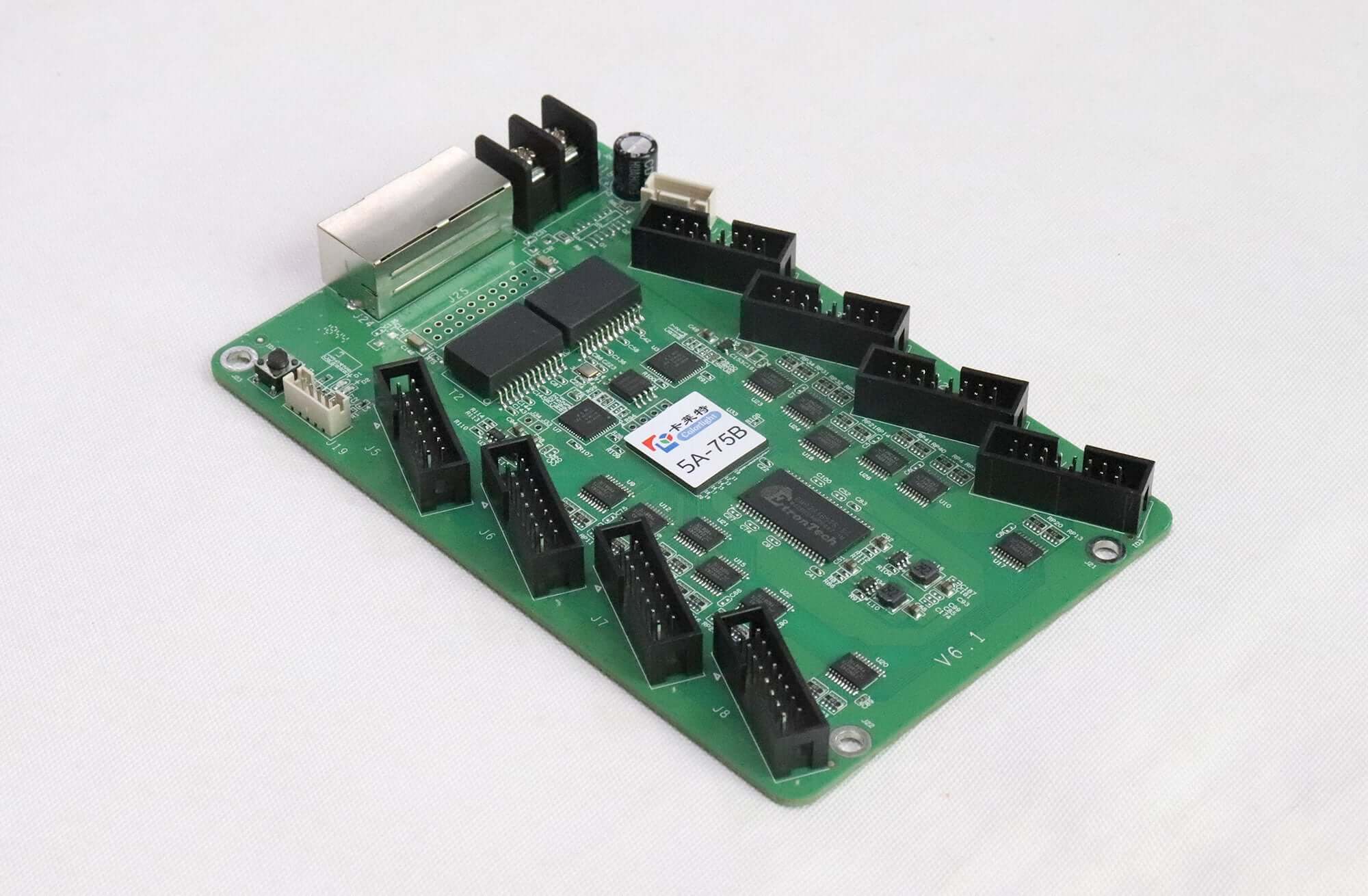

Colorlight 5A-75B HUB75 LED Receiving Card
$ 11.70
Colorlight 5A-75B receiving card with eight HUB75 outputs and two interchangeable Gigabit Ethernet ports. View driver-specific loading limits, DC supply requirements and the V8.3.1 pinout PDF before selecting a replacement.
9978 in stock
Colorlight 5A-75B receiving card for HUB75 LED modules
The Colorlight 5A-75B is an LED receiving card with eight integrated HUB75 outputs. It receives display data through Gigabit Ethernet and distributes it to compatible LED modules inside a cabinet. The integrated connectors remove the need for a separate HUB75 adapter board in a suitable installation.
The specifications below follow 5A-75B Specification V8.3.1. Check the hardware revision on your existing card before using these values for a repair or replacement. The model name alone does not confirm that a card matches your module wiring, driver IC or cabinet configuration.
5A-75B specifications and loading limits
Loading capacity depends on the driver-chip type. The largest value in the specification applies to PWM chips; it should not be used as the capacity for every LED module. Confirm the required cabinet width and height together with the actual module parameters.
| Normal-chip loading | 128 × 1024 pixels |
|---|---|
| PWM-chip loading | 192 × 1024 pixels |
| Shixin-chip loading | 162 × 1024 pixels |
| Scan support | Up to 1/128 scan |
| Module outputs | 8 HUB75 connectors; 16 parallel RGB groups |
| Calibration | 8-bit brightness and 8-bit chromaticity calibration |
| Data connections | 2 interchangeable Gigabit Ethernet ports |
| DC supply | 3.8–5.5 V; use only one power input |
| Power consumption | 3 W, 0.6 A as listed in the specification |
| Dimensions and weight | 145.2 × 91.7 × 18.4 mm; 82 g |
Connections, setup and service checks
The eight module outputs are labeled J1 through J8. Two RJ45 ports automatically recognize input and output direction. The specification recommends CAT5e cable with a transmission distance of up to 100 m. These Ethernet connectors carry the control-system data; confirm the sending-device arrangement before connecting an existing installation.
The board provides two alternative power connection positions. Use one power input only, with correct polarity and a supply within the documented voltage range. Disconnect power before moving module ribbon cables or replacing a receiving card.
The test button provides red, green, blue, white, horizontal-line and vertical-line patterns. Use these patterns to inspect module connections during commissioning. They help check the display path but do not replace the correct receiver configuration or calibration data.
Check compatibility before replacing a card
- Record the existing card model and hardware revision, and photograph both sides.
- Identify the LED module driver IC, scan ratio, resolution and HUB75 pin assignment.
- Back up the working receiver parameters and calibration files before making changes.
- Confirm the sending device, firmware and software arrangement with your installer.
- Test one cabinet before changing cards throughout the screen.
Browse our LED receiving cards for other models. A similar connector layout does not establish interchangeability. For a model check, contact EagerLED with the board photos, cabinet resolution and module information.
Frequently asked questions
Does the 5A-75B need a separate HUB75 adapter?
The card has eight integrated HUB75 connectors, labelled J1–J8. A separate HUB75 adapter is not needed where the module pin assignment and cabinet wiring match these outputs. Confirm the signal mapping before connecting ribbon cables.
Can every module use the maximum 192 × 1024 loading?
No. Specification V8.3.1 lists that limit for PWM driver chips. Normal chips are listed at 128 × 1024 and Shixin chips at 162 × 1024 pixels. Scan mode and frame rate must also be checked.
Can I connect both power inputs?
No. The specification identifies the two power connections as alternatives and instructs users to use only one. The documented supply range is DC 3.8–5.5V.
Does 120Hz or 240Hz operation change the loading limit?
Yes. The specification notes that high frame rates affect loading. Have the driver IC, scan mode, cabinet resolution and target frame rate checked together before configuring the card.
Where can I find the 5A-75B pinout?
Use the specification PDF linked below for the HUB75 pinout, connector diagram and electrical details. Match its V8.3.1 specifications to the actual hardware and firmware revision before applying settings.
Specification and pinout download
| Weight | 0.35 kg |
|---|
Be the first to review “Colorlight 5A-75B HUB75 LED Receiving Card”
You must be logged in to post a review.
Will I be charged with customs and taxes?
The prices displayed on our site are tax-free (in US Dollars), which means you may be required to pay import duties and taxes once you receive your order. Import taxes, duties, and related customs fees will be determined by your local customs office when your order arrives at its final destination.
Please note that these additional charges and taxes are your responsibility, and we do not take any responsibility for them. We are not liable for paying or reimbursing any customs duties, taxes, or related fees. For more details on these charges, please contact your local customs office.
Shipping
We can ship to virtually any address in the world. Note that there are restrictions on some products, and some products cannot be shipped to international destinations..
When you place an order, we will estimate shipping and delivery dates for you based on the availability of your items and the shipping options you choose. Depending on the shipping provider you choose, shipping date estimates may appear on the shipping quotes page.
Please also note that the shipping rates for many items we sell are weight-based. The weight of any such item can be found on its detail page. To reflect the policies of the shipping companies we use, all weights will be rounded up to the next full pound..
Returns Policy
You may return most new, unopened items within 30 days of delivery for a full refund. We'll also pay the return shipping costs if the return is a result of our error (you received an incorrect or defective item, etc.)..
You should expect to receive your refund within four weeks of giving your package to the return shipper, however, in many cases you will receive a refund more quickly. This time period includes the transit time for us to receive your return from the shipper (5 to 10 business days), the time it takes us to process your return once we receive it (3 to 5 business days), and the time it takes your bank to process our refund request (5 to 10 business days).
If you need to return an item, simply login to your account, view the order using the "Complete Orders" link under the My Account menu and click the Return Item(s) button. We'll notify you via e-mail of your refund once we've received and processed the returned item..
Related products


Reviews
There are no reviews yet.