


Huidu HD-R612 LED Receiving Card – 12 HUB75E Ports
$ 14.00
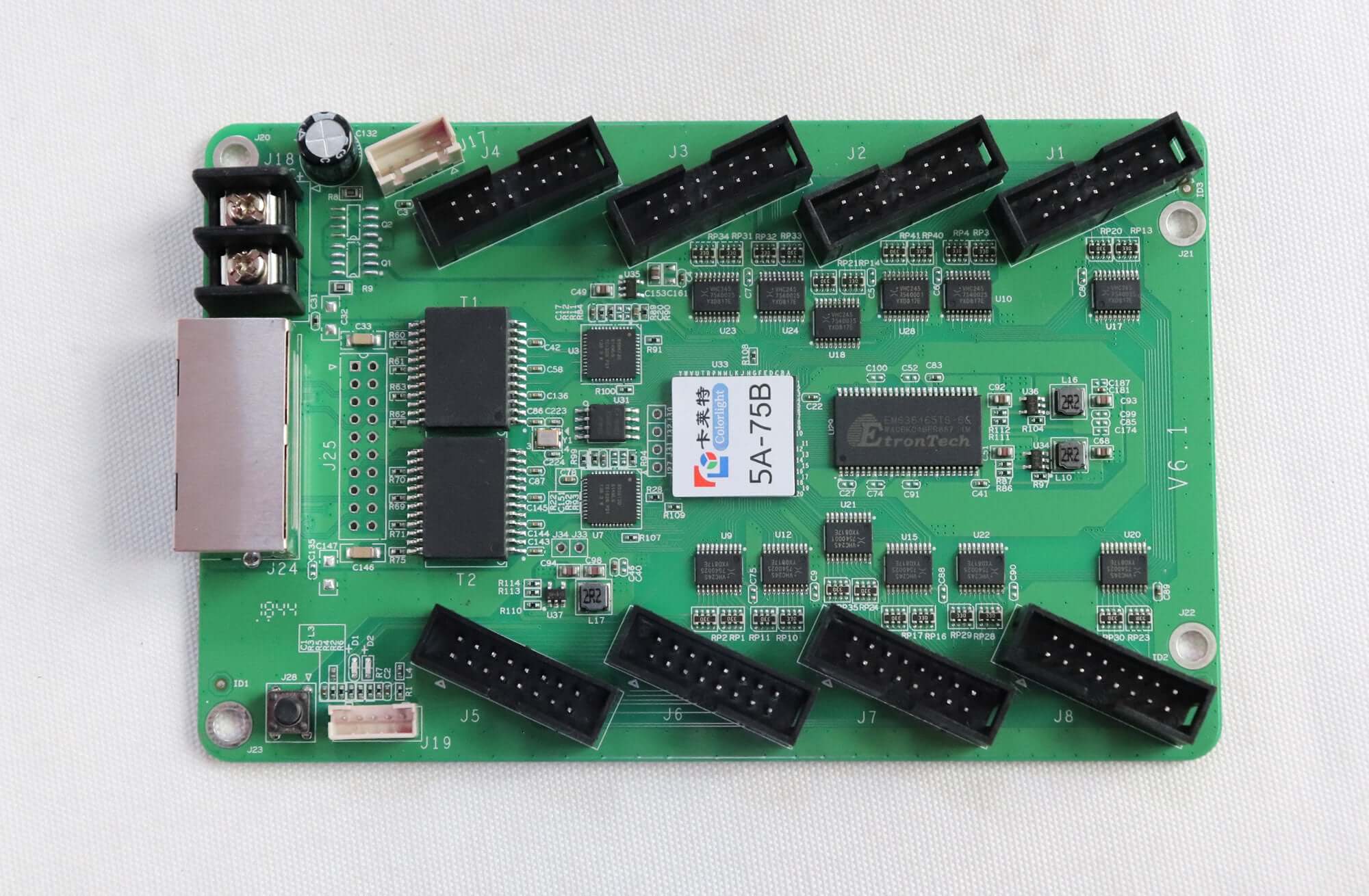
Huidu HD-R612 is a 12-port HUB75E receiving card for LED modules, including LS9929 / LS9919 applications. Review recommended loading, sender compatibility and the specification’s voltage and temperature notes before installation.
1000 in stock
Huidu HD-R612 receiving card for LED screen modules
The HD-R612 has 12 onboard HUB75E outputs and two interchangeable Gigabit Ethernet ports. The linked specification identifies LS9929 / LS9919 driver-chip modules as its dedicated application, while also describing conventional receiving-card use.
Technical parameters
Values below are from HD-R612 specification V0.1. Conflicting supply and temperature entries are kept visible for configuration checks.
| Module interfaces | 12 × HUB75E |
|---|---|
| Primary application | Modules using LS9929 / LS9919 driver chips; also usable as a conventional receiving card |
| Recommended load | 256 × 256 pixels; outdoor module width ≤256, indoor module width ≤128 |
| Conventional-card limit | 128 × 1024, stated in the PDF overview; verify the module configuration |
| Scan / grayscale | Static to 1/64 scan / 256–65,536 levels |
| Network | 2 interchangeable Gigabit Ethernet ports |
| Cable distance | Super Cat5 / Cat6 within 146 m, as stated in V0.1 |
| Power connections | 2 DC power interfaces; either one may be used |
| Supply voltage | 5 V recommended; document ranges differ—see note below |
| Operating temperature | Parameter table: −40°C to 85°C; later °C row: −40°C to 80°C, with incorrect humidity label |
| Storage temperature | −40°C to 105°C |
| Operating humidity | 0–95% |
Power and temperature note: the PDF recommends 5 V but gives three different voltage ranges: 4–6 V, 4.5–5.5 V and 4.2–5.5 V. Its working-temperature table lists −40°C to 85°C, while a later row marked in °C lists −40°C to 80°C and is incorrectly labelled as humidity. Confirm the applicable limits for the supplied revision.
Wiring and commissioning
Connect the sending system or another receiving card through either network port. Use the HUB75E pin definitions in the PDF to match the LED modules. Smart settings support screen layout, and receiving cards may be arranged in any sequence. D1 flashing indicates normal operation; rapid D2 flashing indicates Gigabit recognition and data reception.
HD-R612 frequently asked questions
What LED modules is HD-R612 designed for?
The V0.1 specification describes it as a dedicated receiving card for LS9929 / LS9919 chip modules. It also lists support for common IC modules and most PWM IC modules; confirm the actual driver IC and module wiring.
What is the R612 recommended loading range?
The parameter table recommends 256 × 256 pixels, with outdoor module width no more than 256 and indoor module width no more than 128. The overview separately states a 128 × 1024 conventional-card limit. These statements should be checked against the actual module configuration, not combined into an unrestricted load.
Which sending devices are listed as compatible?
The PDF lists A4, A5, A6, A601, A602 and A603 players; A3, A30, A30+, C10, C10C, C30, C15, C15C, C35 and C35C asynchronous controllers; T901, T901B and T901S synchronous controllers; and VP210 / VP410 processors.
What voltage should I use for the HD-R612?
The document recommends a standard 5 V supply. Its ranges differ: 4–6 V in the parameter table, 4.5–5.5 V at the connector descriptions and 4.2–5.5 V in the technical table. Confirm the supplied board limits before using a voltage other than the recommended 5 V.
Can I check the card without sending normal program content?
The onboard test button is described as providing screen tests for brightness uniformity and module flatness. The card also has power/data status indicators and an external indicator connection.
Specification download
| Weight | 0.4 kg |
|---|
Be the first to review “Huidu HD-R612 LED Receiving Card – 12 HUB75E Ports”
You must be logged in to post a review.
Will I be charged with customs and taxes?
The prices displayed on our site are tax-free (in US Dollars), which means you may be required to pay import duties and taxes once you receive your order. Import taxes, duties, and related customs fees will be determined by your local customs office when your order arrives at its final destination.
Please note that these additional charges and taxes are your responsibility, and we do not take any responsibility for them. We are not liable for paying or reimbursing any customs duties, taxes, or related fees. For more details on these charges, please contact your local customs office.
Shipping
We can ship to virtually any address in the world. Note that there are restrictions on some products, and some products cannot be shipped to international destinations..
When you place an order, we will estimate shipping and delivery dates for you based on the availability of your items and the shipping options you choose. Depending on the shipping provider you choose, shipping date estimates may appear on the shipping quotes page.
Please also note that the shipping rates for many items we sell are weight-based. The weight of any such item can be found on its detail page. To reflect the policies of the shipping companies we use, all weights will be rounded up to the next full pound..
Returns Policy
You may return most new, unopened items within 30 days of delivery for a full refund. We'll also pay the return shipping costs if the return is a result of our error (you received an incorrect or defective item, etc.)..
You should expect to receive your refund within four weeks of giving your package to the return shipper, however, in many cases you will receive a refund more quickly. This time period includes the transit time for us to receive your return from the shipper (5 to 10 business days), the time it takes us to process your return once we receive it (3 to 5 business days), and the time it takes your bank to process our refund request (5 to 10 business days).
If you need to return an item, simply login to your account, view the order using the "Complete Orders" link under the My Account menu and click the Return Item(s) button. We'll notify you via e-mail of your refund once we've received and processed the returned item..
Related products




Reviews
There are no reviews yet.